![[HOME]](/netaicon/homeicon.gif)
![[SEARCH]](/netaicon/srchpage.gif)

![[CURR_LIST]](/netaicon/curlist.gif)


![[BOTTOM]](/netaicon/bottom.gif)
![[HELP]](/netaicon/help.gif)
Seattle City Council Bills and Ordinances
Information modified on April 13, 2006; retrieved on May 9, 2026 4:50 PM
Ordinance 120525
Introduced as Council Bill 113795
Title | |
|---|---|
| AN ORDINANCE relating to energy efficiency and energy conservation: amending Section 22.700.010 of the Seattle Municipal Code ("SMC") that adopted the 2000 Washington State Energy Code with Seattle amendments and amending the Energy Code Sections 1132.2, 1132.3, 1133, 1301, 1310.2, 1312.2, 1322, 1323, 1323.3, 1331, 1333, 1401, 1411.1, 1411.4, 1412.2, 1412.4, 1412.6, 1412.8, 1413, 1413.2, 1413.3, 1414.1, 1416, 1421.1, 1423, 1431.2, 1432.2, 1433, 1436, 1437, 1438, 1440, 1452, 1501, 1510, 1512, 1512.1, 1512.2, 1513.1, 1513.3, 1513.5, 1513.6, 1521, 1530, 1532, and Tables 10-5B, 10-6, 13-1, 14-4, and 15-1, and the title to Chapter 15; adding new Sections 1413.4, 1436.2, 1436.3, 1540, and new Tables 14-1A, 14-1B, 14-1C, 14-1D, 14-1E, 14-1F, 14-1J, 14-1K, 14-1L, 14-1M, and new Section 3.6.5 to Reference Standard 29 of the Energy Code; and repealing Tables 14-1, 14-2, and 14-3 of the Energy Code. | |
Description and Background | |
|---|---|
| Current Status: | Passed |
| Index Terms: | ENERGY-CODES |
| References: | Amending: Ord 120378 |
Legislative History | |
|---|---|
| Sponsor: | WILLS |
| Date Introduced: | August 13, 2001 |
| Committee Referral: | Energy and Environmental Policy |
| City Council Action Date: | September 17, 2001 |
| City Council Action: | Passed |
| City Council Vote: | 9-0 |
| Date Delivered to Mayor: | September 18, 2001 |
|
Date Signed by Mayor: (About the signature date) | September 24, 2001 |
| Date Filed with Clerk: | September 26, 2001 |
| Signed Copy: | PDF scan of Ordinance No. 120525 |
Text | |
|---|---|
|
AN ORDINANCE relating to energy efficiency and energy conservation: amending Section 22.700.010 of the Seattle Municipal Code ("SMC") that adopted the 2000 Washington State Energy Code with Seattle amendments and amending the Energy Code Sections 1132.2, 1132.3, 1133, 1301, 1310.2, 1312.2, 1322, 1323, 1323.3, 1331, 1333, 1401, 1411.1, 1411.4, 1412.2, 1412.4, 1412.6, 1412.8, 1413, 1413.2, 1413.3, 1414.1, 1416, 1421.1, 1423, 1431.2, 1432.2, 1433, 1436, 1437, 1438, 1440, 1452, 1501, 1510, 1512, 1512.1, 1512.2, 1513.1, 1513.3, 1513.5, 1513.6, 1521, 1530, 1532, and Tables 10-5B, 10-6, 13-1, and 15-1, and the title to Chapter 15; adding new Sections 1413.4, 1436.2, 1436.3, 1540, and new Tables 14-1A, 14-1B, 14-1C, 14-1D, 14-1E, 14-1F, 14-1J, 14-1K, 14-1L, 14-1M, and new Section 3.6.5 to Reference Standard 29 of the Energy Code; and repealing Tables 14-1, 14-2, and 14-3 of the Energy Code. BE IT ORDAINED BY THE CITY OF SEATTLE AS FOLLOWS: Section 1. Section 22.700.010, SMC, as last amended by Ordinance 120378 is further amended as follows: 22.700.010 Adoption of the 2000 Washington State Energy Code and local amendments. The 2000 Washington State Energy Code (WAC 51-11) and the amendments thereto adopted by Ordinance 120378 incorporating the Seattle Amendments, and amendments made by the Washington State Building Code Council to the 2000 Washington State Energy Code filed January 5, 2001 (WSR 01-03-010), which is filed with the City Clerk in C.F. 304655, and further amendments made in Ordinance __________ are hereby adopted and by this reference made a part of this subtitle and shall constitute the official Energy Code of the City. The 1997 Washington State Energy Code, and amendments thereto, are hereby repealed. Section 2. Table 10-5B of the Energy Code is amended as follows:
TABLE 10-5B(1)
Group R Occupancy: Default U-Factors for Concrete and Masonry Walls TABLE 10-5B(1) Group R Occupancy: Default U-Factors for Concrete and Masonry Walls 8" CONCRETE MASONRY WALL DESCRIPTION CORE TREATMENT Partial Grout with Ungrouted Solid Cores Grout Empty Loose-fill insulated Perlite Vermiculite Exposed Block, Both Sides 0.40 0.23 0.24 0.43 R-5 Interior Insulation, Wood 0.14 0.11 0.12 0.15 Furring R-6 Interior Insulation, Wood 0.14 0.11 0.11 0.14 Furring R-10.5 Interior Insulation, Wood 0.11 0.09 0.09 0.11 Furring R-8 Interior Insulation, Metal 0.11 0.09 0.09 0.11 Clips R-6 Exterior Insulation 0.12 0.10 0.10 0.12 R-10 Exterior Insulation 0.08 0.07 0.07 0.08 R-9.5 Rigid Polystyrene Integral Insulation, Two Webbed Block 0.11 0.09 0.09 0.12 12" CONCRETE MASONRY WALL DESCRIPTION CORE TREATMENT Partial Grout with Ungrouted Solid Cores Grout Empty Loose-fill insulated Perlite Vermiculite Exposed Block, Both Sides 0.35 0.17 0.18 0.33 R-5 Interior Insulation, Wood 0.14 0.10 0.10 0.13 Furring R-6 Interior Insulation, Wood 0.13 0.09 0.10 0.13 Furring R-10.5 Interior Insulation, Wood 0.11 0.08 0.08 0.10 Furring R-8 Interior Insulation, Metal 0.10 0.08 0.08 0.09 Clips R-6 Exterior Insulation 0.11 0.09 0.09 0.11 R-10 Exterior Insulation 0.08 0.06 0.06 0.08 R-9.5 Rigid Polystyrene Integral Insulation, Two Webbed Block 0.11 0.08 0.09 0.12 8" CLAY BRICK WALL DESCRIPTION CORE TREATMENT Partial Grout with Ungrouted Solid Cores Grout Empty Loose-fill insulated Perlite Vermiculite Exposed Block, Both Sides 0.50 0.31 0.32 0.56 R-5 Interior Insulation, Wood 0.15 0.13 0.13 0.16 Furring R-6 Interior Insulation, Wood 0.15 0.12 0.12 0.15 Furring R-10.5 Interior Insulation, Wood 0.12 0.10 0.10 0.12 Furring R-8 Interior Insulation, Metal 0.11 0.10 0.10 0.11 Clips R-6 Exterior Insulation 0.12 0.11 0.11 0.13 R-10 Exterior Insulation 0.08 0.08 0.08 0.09 6" CONCRETE POURED OR PRECAST WALL DESCRIPTION CORE TREATMENT Partial Grout with Ungrouted Solid Cores Grout Empty Loose-fill insulated Perlite Vermiculite Exposed Block, Both Sides NA NA NA 0.61 R-5 Interior Insulation, Wood NA NA NA 0.16 Furring R-6 Interior Insulation, Wood NA NA NA 0.15 Furring R-10.5 Interior Insulation, Wood NA NA NA 0.12 Furring R-8 Interior Insulation, Metal NA NA NA 0.12 Clips R-6 Exterior Insulation NA NA NA 0.13 R-10 Exterior Insulation NA NA NA 0.09 Notes for Default Table 10-5B(1) 1. Grouted cores at 40" x 48" on center vertically and horizontally in partial grouted walls. 2. Interior insulation values include 1/2" gypsum board on the inner surface. 3. Furring and stud spacing is 16" on center. Insulation is assumed to fill furring space and is not compressed. 4. Intermediate values may be interpolated using this table. Values not contained in this table may be computed using the procedures listed in Standard RS-27.
TABLE 10-5B(2) Other than Group R Occupancy: Default U-Factors for Concrete and Masonry Walls
Framing Rated Assembly Assembly Assembly Type R-Value U Factors U-Factors U-Factor for and of Insul for Solid for Concrete Concrete Depth ation Alone
Concrete Block Walls: Block Walls: Walls Solid Grouted Walls: Partially
Grouted (Cores uninsulated except where
specified) No R0 U0.740 U0.580 U0.480 Framing Ungrouted N.A. N.A. U0.350 Cores Filled with Loose Fill Insulation
Continous Wood Framing 0.75 in. R 3.0 U0.247 U0.226 U0.210 1.5 in. R 6. U0.160 U0.151 U0.143 2.0 in. R10.0 U0.116 U0.111 U0.107 3.5 in. R11.0
U0.094 U0.091 U0.088 3.5 in. R13.0 U0.085 U0.083 U0.080 3.5 in. R15.0 U0.079 U0.077 U0.075 5.5 in. R19.0 U0.060 U0.059 U0.058 5.5 in.
R21.0 U0.057 U0.055 U0.054
Continous Metal Framing at 24 in. on center horizontally
0.75 in. R 3.0 U0.364 U0.321 U0.288 1.5 in. R 6.0 U0.274 U0.249 U0.229 2.0 in. R10.0 U0.225 U0.207 U0.193 3.5in. R11.0 U0.168 U0.158
U0.149 4.0 3.5in. R13.0 U0.161 U0.152 U0.144 4.0 3.5in. R15.0 U0.155 U0.147 U0.140 4.0 5.5in. R19.0 U0.118 U0.113 U0.109 6.0 5.5in. R21.0
U0.113 U0.109 U0.105 6.0
1 in. Metal Clips at 24 in. on center horizontally and 16 in. vertically
1.0 in. R 3.8 U0.210 U0.195 U0.182 1.0 in. R 5.0 U0.184 U0.172 U0.162 1.0 in. R 5.6 U0.174 U0.163 U0.154 1.5 in. R 5.7 U0.160 U0.151
U0.143 1.5 in. R 7.5 U0.138 U0.131 U0.125 1.5 in. R 8.4 U0.129 U0.123 U0.118 2.0 in. R 7.6 U0.129 U0.123 U0.118 2.0 in. R10.0 U0.110
U0.106 U0.102 2.0 in. R11.2 U0.103 U0.099 U0.096 2.5 in. R 9.5 U0.109 U0.104 U0.101 2.5 in. R12.5 U0.092 U0.089 U0.086 2.5 in. R14.0
U0.086 U0.083 U0.080 3.0 in. R11.4 U0.094 U0.090 U0.088 3.0 in. R15.0 U0.078 U0.076 U0.074 3.0 in. R16.8 U0.073 U0.071 U0.069 3.5 in.
R13.3 U0.082 U0.080 U0.077 3.5 in. R17.5 U0.069 U0.067 U0.065 3.5 in. R19.6 U0.064 U0.062 U0.061 4.0 in. R15.2 U0.073 U0.071
U0.070 4.0 in. R20.0 U0.061 U0.060 U0.058 4.0 in. R22.4 U0.057 U0.056 U0.054 5.0 in. R28.0 U0.046 U0.046 U0.045
Continuous Insulation Uninterrupted by Framing
No R 3.0 U0.230 U0.212 U0.197 Framing R 4.0 U0.187 U0.175 U0.164 R 5.0 U0.157 U0.149 U0.141
No R 6.0 U0.136 U0.129 U0.124 Framing R 7.0 U0.120 U0.115 U0.110 R 8.0 U0.107 U0.103 U0.099 R 9.0 U0.097 U0.093
U0.090 R10.0 U0.088 U0.085 U0.083
No R11.0 U0.081 U0.079 U0.076 Framing R12.0 U0.075 U0.073 U0.071 R13.0 U0.070 U0.068 U0.066 R14.0 U0.065 U0.064
U0.062 R15.0 U0.061 U0.060 U0.059
No R16.0 U0.058 U0.056 U0.055 Framing R17.0 U0.054 U0.053 U0.052 R18.0 U0.052 U0.051 U0.050 R19.0 U0.049 U0.048
U0.047 R20.0 U0.047 U0.046 U0.045
Notes for Default Table 10-5B(2)
1. It is acceptable to use the U-factors in Table 10-5B(2) for all concrete and masonry walls, provided that the grouting is equal to or less than that specified.
For ungrouted walls, use the partially-grouted column.
For metal studs and z-furring, use the continuous-metal-framing category.
For discontinuous metal clips 1 inch square or smaller, use the metal-clip category.
For insulation that is attached without any framing members (e.g. glued), use the continuous-insulation-uninterrupted-by-framing category. Continuous insulation may be installed on the interior or exterior of masonry walls, or between stand-alone walls
in multi-layer masonry walls, or on the interior or exterior of the concrete.
2. For Table 10-5B(2), the U-factor includes R-0.17 for exterior air film and R-0.68 for interior air film vertical surfaces. For insulated walls, the U-factor also includes R-0.45 for 0.5 in. gypsum board. U-factors are provided for the following
configurations: (a) Concrete wall: 8-in. normal weight concrete wall with a density of 145 lb/ft3. (b) Solid grouted concrete block wall: 8-in. medium weight ASTM C90 concrete block with a density of 115 lb/ft3 and solid grouted cores.
(c) Partially grouted concrete block wall: 8-in. medium weight ASTM C90 concrete block with a density of 115 lb/ft3 having reinforcing steel every 32 in. vertically and every 48 in. horizontally, with cores grouted in those areas only. Other
cores are filled with insulating material only if there is no other insulation.
3. For walls with insulation contained in a framing layer, the Ufactors in Table 10-5B(2) assume contact (and thermal bridging) between the mass wall and other framing. For wall assemblies with multiple layers where the wood or metal framing layer
does not contact the concrete or masonry layer (i.e. walls with an airspace between the stud wall layer and the mass wall layer), it is acceptable to use the appropriate wood or metal frame wall default U-factors in Tables 10-5 or 10-5A. Note, it is
acceptable to use this approach where the insulation extends beyond the framing and is in contact with the mass wall layer (e.g. a nominal four-inch metal stud containing insulation that is nominally six inches thick and therefore extends two inches
beyond the back of the metal stud).
4. Except for wall assemblies qualifying for note 3, if not taken from Table 10-5B(2), mass wall U-factors shall be determined in accordance with ASHRAE/IESNA Standard 90.1-1999, Appendix A, Section A3.1 and Tables A-5 to A-8, or Section A9.4. If not
taken from Table 10-9, heat capacity for mass walls shall be taken from ASHRAE/IESNA Standard 90.1-1999, Appendix A, Table A-6 or A-7. Section 3. Table 10-6 of the Energy Code is amended as follows: TABLE 10-6 Other than Group R Occupancy: Default U-Factors for Vertical Glazing, Overhead Glazing and Opaque Doors Vertical Glazing (including frame) U-Factor Any Aluminum Vinyl/ Frame w/ Wood thermal Frame break Single 1.45 1.45 1.45 Double 0.90 0.85 0.75 1/2 Inch Air, Fixed 0.75 0.70 0.60 1/2 Inch Air, Low-e(0.40), Fixed 0.60 0.55 0.50 1/2 Inch Air, Low-e(0.10), Fixed 0.55 0.50 0.45 1/2 Inch Argon, Low-e(0.30), Fixed 0.55 0.50 0.45 1/2 Inch Argon, Low-e(0.10), Fixed 0.50 0.45 0.40 The category for aluminum frame with a thermal break is as defined in footnote 7 to Table 10-6A. Overhead Glazing: Sloped Glazing (including frame) U-Factor Any Aluminum Vinyl/W Frame w/ ood thermal Frame break Single 1.74 1.74 1.74 Double 1.08 1.02 0.90 1/2 Inch Air, Fixed 0.90 0.84 0.72 1/2 Inch Air, Low-e(0.40), Fixed 0.72 0.66 0.60 1/2 Inch Air, Low-e(0.10), Fixed 0.66 0.60 0.54 1/2 Inch Argon, Low-e(0.10), Fixed 0.60 0.54 0.48 This default table is applicable to sloped glazing only. (Sloped glazing is a multiple-lite glazed system (similar to a curtain wall) that is mounted at a slope greater than 15 degrees from the vertical plane.) Other overhead glazing shall use the defaults in Table 10-6E. U-Factor Any Frame Vinyl/Wood Frame Single 2.15 2.15 Double 1.45 1.00 Low-e(0.40) or Argon 1.40 0.95 Low-e(0.40) + Argon 1.30 0.85 Low-e(0.20) Air 1.30 0.90 Low-e(0.20) + Argon 1.25 0.80 Triple 1.25 0.80 Opaque Doors U-Factor Uninsulated Metal 1.20 Insulated Metal (Including Fire Door 0.60 and Smoke Vent) Wood 0.50 NOTES: Where a gap width is listed (i.e.: 1/2 inch), that is the minimum allowed. Where a low-emissivity emittance is listed (i.e.: 0.40, 0.20, 0.10), that is the maximum allowed. Where a gas other than air is listed (i.e.: argon), the gas fill shall be a minimum of 90%. Where an operator type is listed (i.e.: fixed), the default is only allowed for that operator type. Where a frame type is listed (i.e.: wood/vinyl), the default is only allowed for that frame type. Wood/Vinyl frame includes reinforced vinyl and aluminum-clad wood. Section 4. Section 1132.2 of the Energy Code is amended as follows: 1132.2 Building Mechanical Systems: Those parts of systems which are altered or replaced shall comply with Chapter 14 of this Code.
1132.2.1 Economizer Capability: Where the air-handling equipment (not including individual water source heat pumps) is being replaced or where 60% or more of the length of the trunk ductwork (not including diffuser runouts) on a floor or
served by a system, whichever is smaller, is being moved or replaced,
a. the system shall comply with the economizer requirements in Section 1433, or
b. the system shall comply with a long-term plan that has been approved by DCLU and that will bring the mechanical system serving that floor into compliance with the economizer requirements in Section 1433 through incremental changes. For projects
using this option, the plan shall be updated whenever the Energy Code is revised. EXCEPTIONS: 1. Where the floor-to-structure (bottom of beam if there is a beam) height is less than 10 feet and the replacement equipment is not installed outdoors or in a mechanical room adjacent to outdoors.
2. The Code Official may approve alternative designs not in full compliance with this Code when existing building or occupancy constraints make compliance impractical or where full compliance would place an unreasonable economic burden on the
project.
1132.2.2 Economizer Capability for Water Source Heat Pump Systems: Where water-source heat pumps are being replaced, the individual heat pump being replaced shall have valves complying with Section 1432.2.2 and
a. the individual heat pump being replaced shall be equipped with economizer coil and operating controls. When the total capacity of all the heat pumps with economizer coil connected to a particular system exceeds 50% of the installed capacity of
that system, then the condenser water system and cooling tower for the entire system shall be capable of providing economizer that complies with Section 1433. (This may necessitate changing the cooling tower and loop piping size.), or
b. the system shall comply with a long-term plan that has been approved by DCLU and that will bring the mechanical system serving that floor into compliance with the economizer requirements in Section 1433 through incremental changes. For projects
using this option, the plan shall be updated whenever the Energy Code is revised. EXCEPTIONS: 1. Systems that comply with the air economizer requirements. 2. The Code Official may approve alternative designs not in full compliance with this Code when existing building or occupancy constraints make compliance impractical or where full compliance would place an unreasonable economic burden on the project. Section 5. Section 1132.3 of the Energy Code is amended as follows: 1132.3 Lighting and Motors: Where the use in a space changes from one use in Table 15-1 to another use in Table 15-1, the installed lighting wattage shall comply with Section 1521 or 1531.
Other (( Where less than 60% of the fixtures in a space enclosed by walls or ceiling-height partitions are new, the installed lighting wattage shall be maintained or reduced. Where 60% or more of the lighting fixtures in a suspended ceiling are new, and the existing insulation is on the suspended ceiling, the roof/ceiling assembly shall be insulated according to the provisions of Chapter 13, Section 1311.2. Where new wiring is being installed to serve added fixtures and/or fixtures are being relocated to a new circuit, controls shall comply with Sections 1513.1 through 1513.5. Where a new lighting panel (or a moved lighting panel) with all new raceway and conductor wiring from the panel to the fixtures is being installed, controls shall comply with Section 1513.6. Those motors which are altered or replaced shall comply with Section 1511. Section 6. Section 1133 of the Energy Code is amended as follows: 1133 Change of Occupancy or Use: Changes of occupancy or use shall comply with the following requirements: a. Any unconditioned space that is altered to become semiheated, cooled, or fully heated, or any semi-heated space that is altered to become cooled or fully heated space shall be required to be brought into full compliance with this Code. For spaces constructed prior to this Code, the installed heating output capacity shall not exceed 16 Btu/h per square foot unless the building envelope complies with Chapter 13. Existing warehouses and repair shops are considered unconditioned space unless they are indicated as conditioned space in DCLU records or they were built after 1980 and they comply with the building envelope requirements for conditioned space in effect at the time of construction. (See the Seattle Mechanical Code for requirements for combustion appliances.) b. Any Group R occupancy which is converted to other than a Group R occupancy shall be required to comply with all of the provisions of Sections 1130 through 1132 of this Code. Section 7. Section 1301 of the Energy Code is amended as follows: 1301 Scope: Conditioned buildings or portions thereof shall be constructed to provide the required thermal performance of the various components according to the requirements of this chapter. Unless otherwise approved by the building official, all spaces shall be assumed to be at least semi-heated. EXCEPTIONS: 1. Greenhouses isolated from any conditioned space and not intended for occupancy. 2. As approved by the building official, spaces not assumed to be at least semi-heated.
3. Unconditioned Group 4. Unstaffed equipment shelters or cabinets used solely for personal wireless service facilities. 5. Parking lot attendant booths no larger than 100 square feet, provided that the opaque components comply with the requirements for semi-heated spaces in Section 1310.2. The heating equipment limitations in Section 1310.2 do not apply. Section 8. Section 1310.2 of the Energy Code is amended as follows:
1310.2 Semi-Heated Spaces: All spaces shall be considered conditioned spaces, and shall comply with the requirements in Section 1310.1 unless they meet the following criteria for semiheated spaces. The installed heating equipment output, in Climate
Zone 1, shall be 3 Btu/(h ( ft2) or greater but not greater than 8 Btu/(h ( ft2) and in Climate Zone 2, shall be 5 Btu/(h ( ft2) or greater but not greater than 12 Btu/(h ( ft2). Heating shall be controlled by a thermostat mounted not lower than the
heating unit and capable of preventing heating above 44 degrees space temperature.
Climate Zone 1
For semi-heated spaces with electric resistance space heat, (1) the building envelope for the semi-heated spaces shall comply with the Prescriptive Building Envelope Option in Section 1320 or (2) the entire building envelope for the semiheated spaces plus the fully heated spaces shall comply with the Component Performance Building Envelope Option in Section 1330. For semi-heated spaces with other space heat, (1) the building envelope for the semi-heated spaces shall comply with the following requirements or (2) the building envelope for the semiheated spaces shall comply with the Prescriptive Building Envelope Option in Section 1320 or (3) the entire building envelope for the semi-heated spaces plus the fully heated spaces shall comply with the Component Performance Building Envelope Option in Section 1330 using the U-factors below for the semi-heated spaces. a. U=0.07 maximum for the opaque roof assembly, or b. continuous R-14 insulation installed entirely outside of the roof structure, or c. R-19 insulation installed inside or within a wood roof structure, or d. R-25 insulation installed inside or within a metal roof structure. e. For opaque wall areas: i. U-0.25 maximum for the overall assembly (or R-3 minimum insulation only for continuous insulation or insulation between wood framing; or R-10 minimum insulation only for insulation between metal framing) for mass walls complying with the heat capacity requirements in Table 13-1, Footnote 2. ii. U-0.14 maximum for the overall assembly (or R-11 minimum insulation only) for metal frame walls. iii. U-0.088 maximum for the overall assembly (or R-11 minimum insulation only) for wood frame and other walls. f. For floors over unconditioned space, U-0.088 maximum for the overall assembly (or R-11 minimum insulation only). g. For fenestration, U-0.90 maximum and a maximum area equivalent to 10% of the gross wall area. It is acceptable to combine semi-heated spaces and fully heated spaces in Target UA calculations. Section 9. Section 1312.2 of the Energy Code is amended as follows: 1312.2 Solar Heat Gain Coefficient and Shading Coefficient: Solar Heat Gain Coefficient (SHGC), shall be determined, certified and labeled in accordance with the National Fenestration Rating Council (NFRC) Standard by a certified, independent agency, licensed by the NFRC.
EXCEPTION: Shading coefficients (SC) or solar heat gain coefficient for the center of glass shall be an acceptable alternate for compliance with solar heat gain coefficient requirements. Shading coefficients or solar heat
gain coefficient for the center of glass for glazing shall be taken from Chapter Note that using the exception for the SHGC for the center-ofglass does not give the full credit for the overall product (including the frame) that the NFRC-certified SHGC does. Though the SHGC for the frame is not zero (the ASHRAE Handbook of Fundamentals indicates that the SHGC can range from 0.11-0.14 for metal frames and from 0.02-0.07 for wood/vinyl/fiberglass frames), the SHGC for the frame is invariable lower than that for the glass. Consequently, an NFRC-certified SHGC will generally be lower. Section 10. Section 1322 of the Energy Code is amended as follows: 1322 Opaque Envelope: Roof/ceilings, opaque exterior walls, opaque doors, floors over unconditioned space, below grade walls, slab on grade floors and radiant floors enclosing conditioned spaces shall be insulated according to Section 1311 and Tables 13-1or 13-2. Compliance with nominal R-values shall be demonstrated for the thermal resistance of the added insulation in framing cavities and/or insulated sheathing only. Nominal R-values shall not include the thermal transmittance of other building materials or air films. For metal frame assemblies used in spaces with electric resistance space heat, compliance shall be demonstrated with the component U-factor for the overall assembly based on the assemblies in Chapter 10. Area-weighted averaging of the R-value is not allowed. When showing compliance with R-values, the minimum insulation Rvalue for all areas of the component shall comply with Table 13-1. When calculating compliance using U-factors, area-weighted averaging is allowed. Where insulation is tapered (e.g. roofs), separate assembly U-factors shall be calculated for each four-foot section of tapered insulation. EXCEPTIONS: 1. Opaque smoke vents are not required to meet insulation requirements. 2. For prescriptive compliance only, a. for glazing areas that are 30% and less of the gross wall area, the insulation of the perimeter edge of an above grade floor slab which penetrates the exterior wall may be reduced to R-5 provided that the glazing U-factor is reduced by U-0.05 below that required in Tables 13-1 and 13-2.
b. for glazing areas that exceed 30% of the gross wall area, the perimeter edge of an above grade floor slab which penetrates the exterior wall may be left uninsulated provided that the glazing U-factor is reduced by U-0.10 below that required
in Tables 13-1 and 13-2.(( 3. For roofs with continuous rigid insulation on the top of the roof, the insulation R-value may be averaged for compliance with minimum prescriptive R-values only, provided that both: a. the minimum insulation is no less than R-5 (but not including area within 6 inches of each roof drain), and b. the area-weighted average insulation is R-46 (in lieu of R-30) for electric resistance space heat and R-27 (in lieu of R-21) for other fuels. Section 11. Section 1323 of the Energy Code is amended as follows: 1323 Glazing: Glazing shall comply with Section 1312 and Tables 13-1 or 13-2. All glazing shall be, at a minimum, double glazing. In addition, all glazing assemblies shall have at least one low-emissivity coating unless the glazing assembly has an overall U-factor that complies with the values in Table 13-1. EXCEPTIONS: 1. Vertical glazing located on the display side of the street level story of a retail occupancy or where there is a street level transparency requirement in the Seattle Land Use Code provided the glazing a. (i) is double-glazed with a minimum 1/2 inch airspace and with a low-e coating having a maximum emittance of e-0.40 in any type of frame or (ii) has an area-weighted U-factor of 0.60 or less. U-factor calculations shall use overall assembly U-factors. When this exception is used there are no SHGC requirements) and b. has a visible transmittance of (i) 0.60 or greater for the center of the glazing assembly in any type of frame or (ii) has an area-weighted visible transmittance for the overall assembly including the frame of 0.52 or greater for fixed glazing and 0.44 or greater for operable glazing. Visible transmittance shall be determined in accordance with Section 1312.2, and,
When this exception is utilized, separate calculations shall be performed for these sections of the building envelope and these values shall not be averaged with any others for compliance purposes. The 75% area may be exceeded on the street level, if the additional glass area is provided from allowances from other areas of the building. 2. Single glazing for ornamental, security, or architectural purposes shall be included in the percentage of total glazing area, U-factor calculation and SHGC as allowed in the Tables 13-1 or 132. The maximum area allowed for the total of all single glazing is 1% of the gross exterior wall area. Section 12. Section 1323.3 of the Energy Code is amended as follows: 1323.3 Solar Heat Gain Coefficient: The area-weighted average solar heat gain coefficient of all glazing shall not be greater than that specified in Tables 13-1 or 13-2 for the appropriate area and U-factor. EXCEPTIONS: 1. Glazing separating conditioned space from semiheated space or unconditioned space. 2. Vertical glazing which is oriented within 45 degrees of north shall be allowed to have a maximum solar heat gain coefficient SHGC-0.10 above that required in Table 13-1. 3. For demonstrating compliance for vertical glazing only, the SHGC in the proposed building shall be allowed to be reduced by using the multipliers in the table below for each glazing product shaded by permanent projections that will last as long as the building itself. Projection SHGC Multiplier SHGC Factor (All Orientations Multiplier except (North-Oriented) North-oriented) 0 0.10 1.00 1.00 <0.10 0.20 0.91 0.95 <0.20 0.30 0.82 0.91 <0.30 0.40 0.74 0.87 <0.40 0.50 0.67 0.84 <0.50 0.60 0.61 0.81 <0.60 0.70 0.56 0.78 <0.70 0.80 0.51 0.76 <0.80 0.90 0.47 0.75 <0.90 1.00 0.44 0.73 Projection factor (PF) is the ratio of the horizontal depth of the external shading projection (A) divided by the sum of the height of the fenestration and the distance from the top of the fenestration to the bottom of the farthest point of the external shading projection (B), in consistent units. (See Exhibit 1323.3.) Section 13. Section 1331 of the Energy Code is amended as follows: 1331 General: Buildings or structures whose design heat loss rate (UAp) and solar heat gain coefficient rate (SHGC * Ap) are less than or equal to the target heat loss rate (UAt) and solar heat gain coefficient rate (SHGC * At) shall be considered in compliance with this section. The stated U-factor, F-factor or allowable area of any component assembly, listed in Tables 13-1 or 13-2, such as roof/ceiling, opaque wall, opaque door, glazing, floor over conditioned space, slab on grade floor, radiant floor or opaque floor may be increased and the U-factor or F-factor for other components decreased, provided that the total heat gain or loss for the entire building envelope does not exceed the total resulting from compliance to the U-factors, F-factors or allowable areas specified in this section.
Section 14. Section 1333 of the Energy Code is amended as follows: 1333 UA Calculations: The target UAt and the proposed UAp shall be calculated using Equations 13-1 and 13-2 and the corresponding areas and U-factors from Table 13-1 or 13-2. For the target UAt calculation, the overhead glazing shall be located in roof/ceiling area and the remainder of the glazing allowed per Table 13-1 or 132 shall be located in the wall area. Where insulation is tapered, separate assembly U-factors shall be calculated in accordance with Section 1322. Section 15. Table 13-1 of the Energy Code is amended as follows: TABLE 13-1 BUILDING ENVELOPE REQUIREMENTS FOR CLIMATE ZONE 1 MINIMUM INSULATION R-VALUES OR MAXIMUM COMPONENT U-FACTORS FOR ZONE 1 Building Components Space Components Heat Type Roofs All Opaque Walls1,2 Opaque Floor Slab Over Other Doors Over On Attic3 Roofs3 Uncond Grade5 Space 1. Electric R-38 or R-30 R-19 or U=0.60 R-30 or R-10 resistance U=0.031 or U=0.062 U=0.029 or heat** U=0.034 F=0.54
2. All R-30 or R-21 ** Compliance with nominal prescriptive R-values requires wood framing. MAXIMUM GLAZING AREAS AND U-FACTORS AND MAXIMUM GLAZING SOLAR HEAT GAIN COEFFICIENTS FOR ZONE 1 Glazing
Space Heat Type Maximum Glazing Area as % of Wall
0% to 20% >20% to 30% >30% to 45%
Maximum Max. Maximum Max. Maximum Max. U-Factor SHGC4 U-Factor SHGC4 U-Factor SHGC4 VG OG VG OG VG OG
1. Electric resistance 0.40 0.48 0.40 0.40 0.48 0.30 PRESCRIPTIVE heat7 PATH NOT ALLOWED
Prescriptive only, not for Target UA or annual
energy analysis
2. All others including 0.55 0.66 0.40 0.55 0.66 0.40 0.45 0.54 0.40 heat pumps and VAV6
VG OG VG OG VG OG VG OG 1. Electri c 0.40 0.80 1.0 0.40 0.80 1.0 PRESCRIPTIVE PATH NOT ALLOWED resistance heat
2. All others 0.90 1.45 1.0 0.75 1.40 1.0 0.60 1.30 0.65 0.50 1.25 0.45 including heat pumps and VAV Footnotes 1. Below Grade Walls: When complying by the prescriptive approach, Section 1322: a) walls insulated on the interior shall use opaque wall values, b) walls insulated on the exterior shall use a minimum of R-10 insulation,
c) walls shall be insulated for the first 10 feet below grade. (There shall be no credit for insulating those portions of below grade walls and footings that are more than 10 feet below grade, and those portions below 10 feet
shall not be included in the gross exterior wall area When complying by the component performance approach, Section 1331: a) walls insulated on the interior shall use the opaque wall values when determining Ubgwt , b) walls insulated on the exterior shall use a target U-factor of U=0.070 for Ubgwt ,
c) the calculations shall include the first 10 feet of walls below grade. (((
2. Concrete Masonry Walls: If the area weighted heat capacity of the total opaque above grade wall is a minimum of 9.0 Btu/ft2 ( degrees F, then the U-factor may be increased to a) 0.11 for interior insulation i) minimum R-11 insulation between wood studs; or ii) minimum R-19 insulation between metal studs; or
iii) minimum R-10 insulation held in place solely by 1 inch metal clips at 24 inches on center vertically and 16 inches on center horizontally; and b) 0.12 for integral and exterior insulation for insulation position as defined in Chapter 2. i) minimum additional R-7 continuous insulation uninterrupted by framing. Individual walls with heat capacities less than 9.0 Btu/ft2 ( degrees F and below grade walls shall meet opaque wall requirements listed above.
Glazing shall comply with the glazing requirements listed above.
Maximum Max. Maximum Max. Maximum Max. Maximum Max. U-Factor SHGC4 U-Factor SHGC4 U-Factor SHGC4 U-Factor SHGC4
VG OG VG OG VG OG VG OG
1. Electric 0.40 0.80 1.00 0.40 0.80 1.00 0.40 0.80 1.00 NOT ALLOWED resistance heat
2. All others 0.90 1.45 1.00 0.75 1.40 1.00 0.65 1.30 0.80 0.60 1.30 0.65 including heat pumps and VAV
3. 4. SHGC (Solar Heat Gain Coefficient per Section 1312.2): May substitute Maximum Shading Coefficient (SC) for SHGC (See Chapter 2 for definition of Shading Coefficient). 5. Radiant Floors: Where insulation is required under the entire slab, radiant floors shall use a minimum of R-10 insulation or F=0.55 maximum. Where insulation is not required under the entire slab, radiant floors shall use R-10 perimeter insulation according to Section 1311.6 or F=0.78 maximum.
6. Prescriptive Alternate (not applicable to Target UA or annual energy analysis): For the prescriptive building envelope option only, for other than electric resistance heat only, glazing may comply with Maximum Glazing Area as % of Wall Maximum U-Factor Maximum
>45% to 50% 0.40 0.48 0.35
7. Prescriptive Alternate for Electric Resistance Space Heat (not applicable to Target UA or annual energy analysis): For glazed wall systems, assemblies with all of the following features are deemed to satisfy the vertical glazing U-factor requirement of U-0.40 and the overhead glazing U-factor of U0.48: a) Double glazing with a minimum 1/2 inch gap width, having a low-emissivity coating with e=0.10 maximum, with 90% minimum argon gas fill, and a non-aluminum spacer (as defined in footnote 1 to Table 10-6B), and
b) Frame that is thermal break aluminum (as defined in footnote Section 16. Section 1401 of the Energy Code is amended as follows: 1401 Scope: This section covers the determination of requirements, system and component performance, control requirements and duct construction.
Section 17. Section 1411.1 of the Energy Code is amended as follows:
1411.1 General: Equipment shall have a minimum performance at the specified rating conditions not less than the values shown in Tables 14-1A through 14-1F EXCEPTION: Water-cooled water-chilling packages that are not designed for operation at ARI Standard 550/590 test conditions (and thus cannot be tested to meet the requirements of Table 14-1C) of 44(F leaving chilled water temperature and 85(F entering condenser water temperature shall have a minimum NPLV rating as shown in Tables 14-1K, L, and M. The table values are only applicable over the following full load design ranges: Leaving Chiller Water Temp.: 40 to 48(F Entering Condenser Water Temp.: 75 to 85(F
Condensing Water Temp.Rise: 5 to 15(F
Chillers designed to operate outside of these ranges are not covered by this Code. Non-standard Part Load Value (NPLV) is defined as single number part-load efficiency figure of merit for chillers references to conditions other than IPLV conditions.
Design condenser water flow rate shall not be less than 2.5 gpm/ton. Gas-fired and oil-fired forced air furnaces with input ratings ( 225,000 Btu/h (65 kW) shall also have an intermittent ignition or interrupted device (IID), and have either mechanical draft (including power venting) or a flue damper. A vent damper is an acceptable alternative to a flue damper for furnaces where combustion air is drawn from the conditioned space. All furnaces with input ratings (225,000 Btu/h (65 kW), including electric furnaces, that are not located within the conditioned space shall have jacket losses not exceeding 0.75% of the input rating. Electric furnaces over 15 kW shall have a minimum of two stages of control for heating. Cooling towers serving chilled water systems with airside economizer complying with Section 1433 without using the exceptions shall be selected to be able to maintain a return condenser water temperature to the tower of 86 F or less at peak design conditions. Cooling towers serving chilled water systems with waterside economizer shall also comply with Section 1433, Exception 3. Hydronic heat pump and other cooling and refrigeration equipment (e.g. icemakers, walk-in coolers) shall not use domestic water only one time before dumping it to waste. No single pass water cooling systems without heat recovery are allowed, except for medical and dental equipment, equipment using less than 1 gpm, and replacement of existing icemakers. However, single pass cooling is allowed during power outages and other emergencies. Section 18. Section 1411.4 of the Energy Code is amended as follows: 1411.4 Packaged and Split System Electric Heating and Cooling Equipment: Packaged and split system electric equipment providing both heating and cooling with a total cooling capacity greater than 20,000 Btu/h shall be a heat pump. EXCEPTION: Unstaffed equipment shelters or cabinets used solely for personal wireless service facilities. Section 19. Section 1412.2 of the Energy Code is amended as follows: 1412.2 Deadband Controls: When used to control both comfort heating and cooling, zone thermostatic controls shall be capable of a deadband of at least 5 degrees F within which the supply of heating and cooling energy to the zone is shut off or reduced to a minimum. EXCEPTIONS: 1. Special occupancy, special usage or code requirements where deadband controls are not appropriate.
2. 3. Thermostats that require manual changeover between heating and cooling modes. Section 20. Section 1412.4 of the Energy Code is amended as follows: 1412.4 Setback and Shut-Off: HVAC systems shall be equipped with automatic controls capable of accomplishing a reduction of energy use through control setback or equipment shutdown during periods of non-use or alternate use of the spaces served by the system. The automatic controls shall a. have a minimum seven-day clock and be capable of being set for seven different day types per week, b. be capable of retaining programming and time setting during loss of power for a period of at least ten hours, and c. include an accessible manual override, or equivalent function (e.g. telephone interface), that allows temporary operation of the system for up to two hours. EXCEPTIONS: 1. Systems serving areas which require continuous operation at the same temperature setpoint. 2. Equipment with full load demands of 2 kW (6,826 Btu/h) or less may be controlled by readily accessible manual off-hour controls. 3. Systems controlled by an occupant sensor that is capable of shutting the system off when no occupant is sensed for a period of up to 30 minutes. 4. Systems controlled solely by a manually-operated timer capable of operating the system for no more than two hours. 1412.4.1 Dampers: Outside air intakes, exhaust outlets and relief outlets serving conditioned spaces shall be equipped with motorized dampers which close automatically when the system is off or upon power failure. Stair shaft and elevator shaft smoke relief openings shall be equipped with normally open (fails open upon loss of power) dampers. These dampers shall remain closed until activated by the fire alarm system or other approved smoke detection system. EXCEPTIONS: 1. Systems serving areas which require continuous operation. 2. Combustion air intakes. 3. Gravity (non-motorized) dampers are acceptable in buildings less than 3 stories in height. Dampers installed to comply with this section, including dampers integral to HVAC equipment, shall have a maximum leakage rate when tested in accordance with AMCA Standard 500 of: a. Motorized dampers: 10 cfm/ft2 of damper area at 1.0 in w.g.
b. Non-motorized dampers: 20 cfm/ft2 of damper area at 1.0 in w.g.,
except that for non-motorized dampers smaller than 24 inches in either dimension: 40 cfm/ft2 of damper area at 1.0 in w.g.
Dampers used as a component of packaged HVAC equipment shall comply with the damper leakage requirements, unless it is the lowest leakage available as a factory option. Drawings shall indicate compliance with this section. 1412.4.2 Optimum Start Controls: Heating and cooling systems with design supply air capacities exceeding 10,000 cfm shall have optimum start controls. Optimum start controls shall be designed to automatically adjust the start time of an HVAC system each day to bring the space to desired occupied temperature levels immediately before scheduled occupancy. The control algorithm shall, as a minimum, be a function of the difference between space temperature and occupied setpoint and the amount of time prior to scheduled occupancy. Section 21. Section 1412.6 of the Energy Code is amended as follows:
1412.6 Combustion Heating Equipment Controls: Combustion heating equipment with a capacity over 225,000 Btu/h shall have modulat EXCEPTIONS: 1. Boilers under 1,000,000 Btu/h input capacity. 2. Radiant Heaters.
3. Systems with multiple boilers which are sequentiallystaged.
Boilers shall comply with the reset requirements in Section 1432.2. Section 22. Section 1412.8 of the Energy Code is amended as follows:
1412.8 Enclosed Parking Garage Ventilation: Garage ventilation fan systems with a total capacity greater than 30,000 cfm shall include the equipment specified in (a) and (b) below. Smaller systems shall include the equipment specified in
either (a) or (b).
a. An automatic control that is capable of staging fans or modulating fan speed as required to maintain carbon monoxide (CO) concentration below a level of 50 ppm as stated in ASHRAE Standard 62. This
b. An automatic control that is capable of shutting off fans or reducing fan speed during periods when the garage is not in use. The system shall be equipped with at least one of the following: i. An automatic timeclock that can start and stop the system under different schedules for seven different day-types per week, is capable of retaining programming and time setting during loss of power for a period of at least 10 hours, and includes an accessible manual override that allows temporary operation of the system for up to 2 hours. ii. An occupant sensor. See the Seattle Building Code for sizing requirements for parking garage ventilation. See the Seattle Mechanical Code, Section 406.5, for other requirements for parking garage ventilation. Section 23. Section 1413 of the Energy Code is amended as follows: 1413 Air and Water Economizers Section 24. Section 1413.2 of the Energy Code is amended as follows: 1413.2 Control: Air and water economizers shall be controlled by a control system capable of determining if outside air can meet part or all of the building's cooling loads. Section 25. Section 1413.3 of the Energy Code is amended as follows:
1413.3 Integrated Operation EXCEPTIONS:
1. 2. Water cooled chillers with waterside economizer. Section 26. The Energy Code is amended by adding a new Section 1413.4 to read as follows: 1413.4 Economizer Heating System Impact: Any HVAC system that increases the building heating energy use during economizer operation is not allowed (e.g. single-fan/dual-duct systems and multizone systems). EXCEPTIONS: 1. Where the heating is allowed by Section 1435. 2. Water source heat pump systems that comply with Section 1433, Exception 3. Note that single-fan/dual-duct systems and multizone systems do not comply with this requirement. This is because economizer operation lowers the temperature of the air entering the hot deck heating coil, increasing its energy use. In order to use this type of system, a water economizer must be used, or the system must meet one of the economizer exceptions and have neither type of economizer. (Another resolution is to use a dual-fan/dual-duct system where the hot deck fan supplies only return air or return air plus minimum ventilation air.) This requirement will not affect three-deck multizone since they cannot work with an air economizer in any case (it would make the neutral deck a cold deck). An exception to the heating impact is provided for economizers on VAV systems that cause zone level heating to increase due to a reduction in supply air temperature. Reducing supply air temperatures on a cooling-VAV system will reduce fan energy (particularly if the system has a variable speed drive), offsetting the energy lost due to increased reheat energy. See the discussion and diagrams of Section 6.3.1.4 of ASHRAE/IESNA Standard 90.1-1999 in the Users Manual. Section 27. Section 1414.1 of the Energy Code is amended as follows:
1414.1 Sealing: Duct work which is designed to operate at pressures above 1/2 inch water column static pressure shall be sealed
1.
2. Static pressure: 3. Static pressure: above 3 inches; seal all transverse joints, longitudinal seams and duct wall penetrations.
All low-pressure supply and return air systems not located entirely within the conditioned space, including the unconditioned side of enclosed stud bays or joist cavities/spaces used to transport air, shall be securely fastened and sealed. Ductwork shall be sealed using welds, gaskets, mastic, or mastic-plusembedded-fabric tape. Enclosed stud bays or joist cavities/spaces used to transport air shall be sealed using mastic-plus-embeddedfabric tape or, when drywall is used to enclose the air system, drywall mud and tape. Duct tape is not permitted as a sealant on any ducts. EXCEPTION: Fibrous glass duct systems installed in accordance with standard UL 181A and flexible duct systems installed in accordance with standard UL 181B may use tapes listed for these systems. Note that longitudinal seams are joints oriented in the direction of airflow. Transverse joints are connections of two duct sections oriented perpendicular to airflow. Duct wall penetrations are openings made by any screw fastener, pipe, rod or wire. All other connections are considered transverse joints, including but not limited to spin-ins, taps and other branch connections, access door frames and jambs, duct connections to equipment. Section 28. Section 1416 of the Energy Code is amended as follows: 1416 Mechanical Systems Commissioning and Completion Requirements
1416.1 General. Commissioning is a systematic process of verification and documentation that ensures that the selected building systems have been designed, installed, and function properly, efficiently, and can be maintained in accordance with
the contract documents in order to satisfy the building owner's design intent and operational requirements. Drawing notes shall require commissioning and completion requirements in accordance with this section. Drawing notes may refer to
specifications for further requirements.
1416.1.1 Simple Mechanical Systems. For simple mechanical systems, as defined in Section 1421, and for warehouses and semiheated spaces, commissioning shall include, as a minimum:
a. A Commissioning Plan, b. System Testing and Balancing, c. Controls Functional Performance Testing, d. A Preliminary Commissioning Report, e. Post
Construction Documentation in the form of O&M and Record Drawing Review, and f. A Final Commissioning Report.
1416.1.2 All Other Mechanical Systems. For all other mechanical systems, commissioning shall include, as a minimum: a. A Commissioning Plan, b. System Testing and Balancing, c. Equipment Functional Performance Testing, d. Controls Functional Performance Testing, e. A Preliminary Commissioning Report, f. Post Construction Documentation (all), and g. A Final Commissioning Report.
1416.2 Commissioning Requirements
1416.2.1 General. Drawing notes shall require commissioning in accordance with this section. Drawing notes may refer to specifications for further commissioning requirements.
1416.2.2 Commissioning Plan. The Plan shall require tests mandated by this section be performed and the results recorded. The Plan shall require preparation of preliminary and final reports of test procedures and results as described herein. At a
minimum, the Plan shall identify the following for each test: a. A detailed explanation of the original design intent. b. Equipment and systems to be tested, including the extent of tests, c. Functions to be tested (for example calibration, economizer control, etc.), d. Conditions under which the test shall be performed (for example winter and summer design conditions, full outside air, etc.), and
e. Measurable criteria for acceptable performance.
1416.2.3 Systems Balancing
1416.2.3.1 General. Construction documents shall require that all HVAC systems be balanced in accordance with generally accepted engineering standards. Air and water flow rates shall be measured and adjusted to deliver final flow rates within 10% of
design rates, except variable flow distribution systems need not be balanced upstream of the controlling device (for example, VAV box or control valve). Construction documents shall require a written balance report be provided to the owner. Drawing
notes may refer to specifications for further systems balancing requirements.
1416.2.3.2 Air Systems Balancing. Air systems shall be balanced in a manner to first minimize throttling losses then, for fans with system power of greater than 1 hp, fan speed shall be adjusted to meet design flow conditions.
1416.2.3.3 Hydronic Systems Balancing: Hydronic systems shall be proportionately balanced in a manner to first minimize throttling losses, then the pump impeller shall be trimmed or pump speed shall be adjusted to meet design flow conditions. Each
hydronic system shall have either the ability to measure pressure across the pump, or test ports at each side of each pump. EXCEPTIONS:
1. Pumps with pump motors of 10 hp or less. 2. When throttling results in no greater than 5% of the nameplate horsepower draw above that required if the impeller was trimmed.
1416.2.4 Functional Performance Testing
1416.2.4.1 General. Drawing notes shall require commissioning in accordance with this section. Drawing notes may refer to specifications for further commissioning requirements.
1416.2.4.2 Equipment/Systems Testing. Functional Performance Testing shall demonstrate the correct installation and operation of each component, system, and system-to-system intertie relationship in accordance with approved plans and specifications.
This demonstration is to prove the operation, function, and maintenance serviceability for each of the Commissioned systems. Testing shall include all modes of operation, including:
a. All modes as described in the Sequence of Operation, b. Redundant or automatic back-up mode, c. Performance of alarms, and d. Mode of operation upon a loss of power and restored
power.
1416.2.4.3 Controls Testing: HVAC control systems shall be tested to ensure that control devices, components, equipment and systems are calibrated, adjusted and operate in accordance with approved plans and specifications. Sequences of operation
shall be functionally tested to ensure they operate in accordance with approved plans and specifications.
1416.2.5 Post Construction Commissioning
1416.2.5.1 General: Construction documents shall require post construction commissioning be provided to the building owner prior to date of final acceptance. Drawing notes may refer to specifications for further commissioning requirements. Post
construction commissioning shall include, as a minimum, review and approval of Operation and Maintenance Materials, Record Drawings, and Systems Operational Training.
1416.2.5.2 Operation and Maintenance Materials: The O&M Materials shall be in accordance with industry accepted standards and shall include, at a minimum, the following: a. Submittal data stating equipment size and selected options for each piece of equipment requiring maintenance. b. Operation and maintenance manuals for each piece of equipment requiring maintenance, except equipment not furnished as part of the project. Required routine maintenance actions shall be clearly identified. c. Names and addresses of at least one service agency. d. HVAC controls system maintenance and calibration information, including wiring diagrams, schematics, and control sequence descriptions. Desired or field determined set points shall be permanently recorded on control drawings at control devices, or, for digital control systems, in programming comments. e. A complete written narrative of how each system and piece of equipment is intended to operate including: i. A detailed explanation of the original design intent. ii. The basis of design (how the design was selected to meet the design intent). + iii. A detailed explanation of how new equipment is to interface with existing equipment or systems (where applicable). iv. Suggested control set points.
NOTE: Sequence of Operation is not acceptable as a narrative for this requirement.
1416.2.5.3 Record Drawings: Record drawings shall include, as a minimum, the location and performance data on each piece of equipment, general configuration of duct and pipe distribution system, including sizes, and the terminal air and water design
flow rates of the actual installation.
1416.2.5.4 Systems Operational Training: The training of the appropriate maintenance staff for each equipment type and or system shall include, as a minimum, the following: a. System/Equipment overview (what it is, what it does and which other systems and or equipment does it interface with).
b. Review of the available O&M materials. c. Review of the Record Drawings on the subject system/equipment. d. Hands-on demonstration of all normal maintenance procedures, normal operating modes, and
all emergency shutdown and start-up procedures.
1416.2.6 Commissioning Reports
1416.2.6.1 General. Drawing notes shall require commissioning in accordance with this section. Drawing notes may refer to specifications for further commissioning requirements.
1416.2.6.2 Preliminary Commissioning Report: A preliminary report of commissioning test procedures and results shall be completed and provided to the Owner. The Preliminary Commissioning Report shall identify: a. Deficiencies found during testing required by this section which have not been corrected at the time of report preparation and the anticipated date of correction. b. Deferred tests which cannot be performed at the time of report preparation due to climatic conditions.
c. Climatic conditions required for performance of the deferred tests, and the anticipated date of each deferred test.
1416.2.6.3 Final Commissioning Report: A complete report of test procedures and results shall be prepared and filed with the Owner. The Final Commissioning Report shall identify: a. Results of all Functional Performance Tests. b. Disposition of all deficiencies found during testing, including details of corrective measures used or proposed. c. All Functional Performance Test procedures used during the commissioning process including measurable criteria for test acceptance, provided herein for repeatability. EXCEPTION: Deferred tests which cannot be performed at the time of report preparation due to climatic conditions.
1416.3 Acceptance Requirements
1416.3.1 General. Drawing notes shall require commissioning in accordance with this section. Drawing notes may refer to specifications for further commissioning requirements. Buildings or portions thereof, required by this Code to comply with this
section, shall not be issued the following certificates until such time that the building official determines that the appropriate commissioning requirements dictated by this section have been completed and provided.
1416.3.2 Acceptance: Buildings or portions thereof, required by this Code to comply with this section, shall not be issued a final certificate of occupancy until such time that the building official determines that the preliminary commissioning report
required by this section has been completed.
1416.3.1 General: Construction documents shall require that all HVAC systems be balanced in accordance with generally accepted engineering standards. Air and water flow rates shall be measured and adjusted to deliver final flow rates within 10% of
design rates, except variable flow distribution systems need not be balanced upstream of the controlling device (for example, VAV box or control valve). Construction documents shall require a written balance report be provided to the owner.
1416.3.2 Air System Balancing: Air systems shall be balanced in a manner to first minimize throttling losses then, for fans with system power of greater than 1 hp, fan speed shall be adjusted to meet design flow conditions.
1416.3.3 Hydronic System Balancing: Hydronic systems shall be proportionately balanced in a manner to first minimize throttling losses, then the pump impeller shall be trimmed or pump speed shall be adjusted to meet design flow conditions. Each hydronic
system shall have either the ability to measure pressure across the pump, or test ports at each side of each pump.
1416.4.1 Simple Systems: For simple systems, as defined in Section 1421, and for warehouses and semiheated spaces, HVAC control systems shall be tested to ensure that control devices, components, equipment and systems are calibrated, adjusted and
operate in accord with approved plans and specifications. Sequences of operation shall be functionally tested to ensure they operate in accord with approved plans and specifications. A complete report of test procedures and results shall be prepared and
filed with the owner. Drawing notes shall require commissioning in accordance with this paragraph.
1416.4.2 Other Systems: All other HVAC control systems, and other automatically controlled systems for which energy consumption, performance, or mode of operation are regulated by this code, shall be tested to ensure that control devices, equipment and
systems are calibrated, adjusted and operate in accord with approved plans and specifications. Sequences of operation shall be functionally tested to ensure they operate in accord with approved plans and specifications.
1416.4.2.1 Documentation: Drawing notes shall require commissioning in accordance with this section. Drawing notes may refer to specifications for further commissioning requirements. Plans and specifications shall require tests mandated by this section
be performed and the results recorded. Plans and specifications shall require preparation of preliminary and final reports of test procedures and results as described in 1416.4.2.2. Plans and specifications shall identify the following for each
test:
1416.4.2.2 Commissioning Reports
1416.4.2.2.1 Preliminary Commissioning Report: A preliminary commissioning report of test procedures and results shall be prepared. The preliminary report shall identify:
1416.4.2.2.2 Final Commissioning Report: A complete report of test procedures and results shall be prepared and filed with the owner.
1416.4.2.3 Acceptance: Buildings or portions thereof, required by this code to comply with this section, shall not be issued a final certificate of occupancy until such time that the building official determines that the preliminary commissioning report
required by this section has been completed. Section 29. Section 1421.1 of the Energy Code is amended as follows:
1421.1 System Sizing Limits: Installed space heating equipment output shall not exceed EXCEPTIONS: 1. For equipment which provides both heating and cooling in one package unit, compliance need only be demonstrated for either the space heating or space cooling system size. 2. Equipment sized in accordance with Section 1431.2. Section 30. Section 1423 of the Energy Code is amended as follows:
1423 Economizers: Economizers meeting the requirements of Section 1413 shall be installed on single package unitary fan-cooling units having Section 31. Section 1431.2 of the Energy Code is amended as follows:
1431.2 System Sizing Limits: Heating and cooling design loads for the purpose of sizing systems shall be determined in accordance with one of the procedures described in Chapter
Building mechanical systems for all buildings which provide space heating and/or space cooling shall be sized no greater than For buildings with a total equipment cooling capacity of 300 tons and above, equipment shall have multiple unloadings or no one unit shall have a capacity of more than 2/3 of the load. EXCEPTIONS: The following limited exemptions from the sizing limit shall be allowed, however, in all cases heating and/or cooling design load calculations shall be submitted. 1. For a single piece of equipment which has both heating and cooling capability, only one function, either the heating or the cooling, need meet the requirements of this section. Capacity for the other function shall be, within available equipment options, the smallest size necessary to meet the load.
2.
4. A maximum sizing limit of 150% is allowed for fan systems which a. have both a capacity of 5,000 cfm or greater and which have a minimum outside air supply of 70% or greater of the total air circulation, and b. have a heat recovery system complying with Section 1436 without using any of the exceptions. Section 32. Section 1432.2 of the Energy Code is amended as follows: 1432.2 Systems Temperature Reset Controls 1432.2.1 Air Systems for Multiple Zones: Systems supplying heated or cooled air to multiple zones shall include controls which automatically reset supply air temperatures by representative building loads or by outside air temperature. Temperature shall be reset by at least 25% of the design supply-air-to-room-air temperature difference. EXCEPTION: Where specified humidity levels are required to satisfy process needs, such as computer rooms or museums.
1432.2.2 Hydronic Systems: Systems with a design capacity of EXCEPTIONS: 1. Hydronic systems that use variable flow devices complying with Section 1438 to reduce pumping energy. 2. Steam boilers. 3. Systems that provide heating with 100usedF or lower supply temperature (e.g. water source heat pump loops). To limit the heat loss from the heat rejection device (cooling tower), for hydronic heat pumps connected to a common heat pump water loop with central devices for heat rejection (e.g., cooling tower), a. If a closed-circuit tower (fluid cooler) is used, either an automatic valve shall be installed to bypass all but a minimal flow of water around the tower (for freeze protection), or low leakage positive closure dampers shall be provided. b. If an open-circuit tower is used directly in the heat pump loop, an automatic valve shall be installed to bypass all heat pump water flow around the tower. c. If an open-circuit tower is used in conjunction with a separate heat exchanger to isolate the tower from the heat pump loop, then heat loss shall be controlled by shutting down the circulation pump on the cooling tower loop. For hydronic heat pumps connected to a common heat pump water loop with central devices for heat rejection (e.g., cooling tower) and having a total pump system power exceeding 10 hp, each hydronic heat pump shall have a. a two-position two-way (but not three-way) valve, or
b. a variable head pressure two-way (water regulating) control valve or pump.
For the purposes of this section, pump system power is the sum of the nominal power demand (i.e. nameplate horsepower at nominal motor efficiency) of motors of all pumps that are required to operate at design conditions to supply fluid from the heating
or cooling source to all heat transfer devices (e.g., coils, heat exchanger) and return it to the source. This converts the system into a variable flow system and, as such, the primary circulation pumps shall comply with the variable flow requirements
in Section 1438. Section 33. Section 1433 of the Energy Code is amended as follows: 1433 Economizers: Economizers meeting the requirements of Section 1413 shall be installed on the following systems, including those serving computer server rooms, electronic equipment, radio equipment, telephone switchgear:
a. Single package unitary fan-cooling units installed outdoors or in a mechanical room adjacent to outdoors with a total cooling capacity greater than 20,000 Btu/h.
b. Other individual fan-cooling units with The total capacity of all units without economizers (i.e. these units complying with a or b above) shall not exceed 240,000 Btu/h per building, or 10% of its aggregate cooling (economizer) capacity, whichever is greater. That portion of the equipment serving Group R occupancy is not included in determining the total capacity of all units without economizers in a building. EXCEPTIONS: 1. Systems with air or evaporatively cooled condensers and that either one of the following can be demonstrated to the satisfaction of the enforcing agency: a. Special outside air filtration and treatment, for the reduction and treatment of unusual outdoor contaminants, makes an air economizer infeasible. b. The use of outdoor air cooling affects the operation of other systems (such as humidification, dehumidification and supermarket refrigeration systems) so as to increase the overall building energy consumption. 2. Systems for which at least 75% of the annual energy used for mechanical cooling is provided from site-recovery or site-solar energy source.
3. a. Design economizer cooling capacity: The calculated system cooling load served by all terminal equipment without airside economizer at 45 degrees F db/40 degrees F wb, with solar and internal loads the same as those calculated for peak cooling load except for outside air temperature. b. Design economizer fluid supply temperature: The design fluid supply temperature delivered to the terminal cooling coils when in economizer operation at 45 degrees F db/40 degrees F wb. c. Equipment which rejects heat to outdoors shall be sized to provide design economizer cooling capacity and design economizer fluid supply temperature at an ambient temperature of 40 degrees F wb. However, air cooled heat rejection equipment shall be sized to provide design economizer cooling capacity and design economizer fluid supply temperature at an ambient temperature of 35 degrees F db. This allowance for air-cooled equipment is applicable only to existing buildings and limited to a maximum of 20 tons per building. d. Terminal cooling coils shall be sized for design economizer cooling capacity at the design economizer fluid supply temperature. However, hydronic heat pumps with terminal cooling coils shall be sized to provide 45% of design economizer capacity at design economizer fluid supply temperature. Section 34. Section 1436 of the Energy Code is amended as follows: 1436 Heat Recovery 1436.1 Fan Systems: Fan systems which have both a capacity of 5,000 cfm or greater and which have a minimum outside air supply of 70% or greater of the total air circulation shall have a heat recovery system with at least 50% recovery effectiveness. Fifty percent heat recovery effectiveness shall mean an increase in the outside air supply temperature at design heating conditions of one half the difference between the outdoor design air temperature and 65 degrees F. Provision shall be made to bypass or control the heat recovery system to permit air economizer operation as required by Section 1433. Heat recovery energy may be provided from any siterecovered or site-solar source. EXCEPTIONS: 1. Laboratory systems equipped with both variable air volume supply and variable air volume or two-speed exhaust fume hoods, provided that an instruction label is placed on the face of the hood that matches Exhibit 14-1. Exhibit 14-1 INSTRUCTIONS TO OPERATOR To be in compliance with the Seattle Energy Code, this fume hood is designed to operate as variable air volume (VAV) by adjusting the sash or controller. Maintain sash in the minimum position during use and close totally when the fume hood is not in use. 2. Systems serving spaces heated to less than 60 degrees F. 3. Systems which can be shown to use as much energy with the addition of heat recovery equipment as without it. 4. Systems exhausting toxic, flammable, paint exhaust or corrosive fumes making the installation of heat recovery equipment impractical. 5. Type I commercial kitchen hoods. Section 35. The Energy Code is amended by adding a new Section 1436.2 to read as follows: 1436.2 Condensate Systems: On-site steam heating systems shall have condensate recovery. Section 36. The Energy Code is amended by adding a new Section 1436.3 to read as follows: 1436.3 Heat Recovery for Service Water Heating: Condenser heat recovery systems shall be installed for heating or preheating of service hot water provided all of the following are true: a. The facility operates 24 hours a day. b. The total installed heat rejection capacity of the watercooled systems exceeds 6,000,000 Btu/h of heat rejection. c. The capacity of service water heating equipment exceeds 1,000,000 Btu/h. The required heat recovery system shall have the capacity to provide the smaller of: a. 60% of the peak heat rejection load at design conditions, or b. preheat of the peak service hot water draw to 85F. EXCEPTIONS: 1. Facilities that employ condenser heat recovery for space heating with a heat recovery design exceeding 30% of the peak water-cooled condenser load at design conditions. 2. Facilities that provide 60% of their service water heating from site solar or site recovered energy or from other sources. Section 37. Section 1437 of the Energy Code is amended as follows: 1437 Electric Motor Efficiency: Design A & B squirrel-cage, Tframe induction permanently wired polyphase motors of 1 hp or more having synchronous speeds of 3,600, 1,800 and 1,200 rpm shall have a nominal full-load motor efficiency no less than the corresponding values for energy efficient motors provided in Table 14-4. EXCEPTIONS: 1. Motors used in systems designed to use more than one speed of a multi-speed motor. 2. Motors used as a component of the equipment meeting the minimum equipment efficiency requirements of Section 1411 and Tables 14-1 and 14-2 provided that the motor input is included when determining the equipment efficiency. 3. Motors that are an integral part of specialized process equipment. 4. Where the motor is integral to a listed piece of equipment for which no complying motor has been approved. Fan motors less than 1 hp in series terminal units shall a. be electronically-commutated motors, or b. have a minimum motor efficiency of 65% when rated in accordance with NEMA Standard MG-1 at full load rating conditions. EXCEPTION: Until June 30, 2002, systems where the cooling design air temperature from the central fan is less than 48 F. Section 38. Section 1438 of the Energy Code is amended as follows: 1438 Variable Flow Systems and System Criteria: For fans and pumps greater than 10 horsepower, where the application involves variable flow, and water source heat pump loops subject to the requirements of Section 1432.2.2, there shall be
At the time this Code was adopted, very few technologies could be shown to meet the criteria in option 2. Variable inlet vanes, throttling valves (dampers), scroll dampers or bypass circuits shall not be allowed. Static pressure sensors used to control variable air volume fans shall be placed in a position such that the controller set point is no greater than 1/3 the total design fan static pressure. For systems with direct digital control of individual zone boxes reporting to the central control panel, there shall be static pressure reset controls and the static pressure set point shall be reset based on the zone requiring the most pressure; i.e., the set point is reset lower until one zone damper is nearly wide open. Section 39. Section 1440 of the Energy Code is amended as follows: 1440 Service Water Heating: Service water heating equipment shall comply with the applicable efficiencies in Tables 14-1A through 14-1M. Effective January 1, 2004, commercial clothes washers installed in Seattle shall have a minimum modified energy factor (MEF) of 1.26. The MEF definition and test procedure set forth at 10 C.F.R. Part 430 (Energy Conservation Program For Consumer Products), as amended, is incorporated into this section by reference. Commercial clothes washers are defined as all clothes washers a. installed for use on fee basis, e.g. coinor cardoperated; b. not covered by federal residential clothes washer efficiency standards; and c. having a capacity of 20 lbs. or less. Section 40. Section 1452 of the Energy Code is amended as follows: 1452 Pool Water Heaters: Pool water heaters using electric resistance heating as the primary source of heat are prohibited for all pools. Heat pump pool heaters shall have a minimum COP of 4.0 determined in accordance with ASHRAE Standard 146, Method of Testing for Rating Pool Heaters. Other pool heating equipment shall comply with the applicable efficiencies in Tables 14-1A through 14-1M. Section 41. The Energy Code is amended by adding a new Table 14-1A to read as follows: Table 14-1A Electrically Operated Unitary Air Conditioners and Condensing Units Minimum Efficiency Requirements Equipment Type Size Category Sub-Category Minimum Test or Rating Efficiency Procedure Condition Air < 65,000 Btu/h Split System 10.0 SEER ARI Conditioners, 210/240 Air Cooled Single 9.7 SEER Package within65,000 Btu/h Split System 10.3 EERc and and < 135,000 Btu/h Single Package within135,000 Btu/h Split System 9.7 EERc ARI and and 340/360 < 240,000 Btu/h Single Package within 240,000 Btu/h Split System 9.5 EERc and and <760,000 Btu/h Single 9.7 IPLVc Package 760,000 Btu/h Split System 9.2 EERc and Single 9.4 IPLVc Package Air < 65,000 Btu/h Split System 12.1 EER ARI Conditioners, and 210/240 Water and Single Evaporatively Package Cooled within 65,000 Btu/h Split System 11.5 EERc and and < 135,000 Btu/h Single Package within135,000 Btu/h Split System 11.0 EERc ARI and and 340/360 ommunity240,000 Btu/h Single Package > 240,000 Btu/h Split System 11.0 EERc and 10.3 Single IPLVc Package Condensing within135,000 Btu/h 10.1 EER ARI 365 Units, 11.2 IPLV Air Cooled Condensing within135,000 Btu/h 13.1 EER Units, 13.1 IPLV Water or Evaporatively Cooled a Reserved. b IPLVs are only applicable to equipment with capacity modulation. c Deduct 0.2 from the required EERs and IPLVs for units with a heating section other than electric resistance heat. No deduction for equipment with no heat. Section 42. The Energy Code is amended by adding a new Table 14-1B to read as follows: Table 14-1B Electrically Operated Unitary and Applied Heat Pumps - Equipment Type Size Category Sub-Category Minimum Test or Rating Efficiency Procedure Condition Air Cooled, < 65,000 Split System 10.0 SEER ARI 210/240 (Cooling Mode) Btu/h Single 9.7 SEER Package within65,000 Btu/h Split System 10.1 EERc and and < 135,000 Single Btu/h Package within135,000 Split System 9.3 EERc ARI 340/360 Btu/h and and <240,000 Single Btu/h Package 240,000 Btu/h Split System 9.0 EERc and 9.2 IPLVc Single Package Water-Source < 17,000 86 degrees F Entering 11.2 EER ARI/ISO-1325 (Cooling Mode) Btu/h Water 6-1 17,000 Btu/h 86 degrees F Entering 12.0 EER ARI/ISO-1325 and Water 6-1 <65,000 Btu/h within65,000 Btu/h 86 degrees F Entering 12.0 EER ARI/ISO-1325 and Water 6-1 < 135,000 Btu/h Groundwater-Source < 135,000 59 degrees F Entering 16.2 EER ARI/ISO-1325 Btu/h Water 6-1 (Cooling Mode) Ground Source < 135,000 77 degrees F Entering 13.4 EER ARI/ISO-1325 (Cooling Mode) Btu/h Water 6-1 Air Cooled < 65,000 Split System 6.8 HSPF ARI 210/240 (Heating Mode) Btu/hd (Cooling Capacity) Single 6.6 HSPF Package within65,000 Btu/h 47 degrees F db/43 degrees F 3.2 COP and wb Outdoor < 135,000 Air 2.2 COP Btu/h 17 degrees F db/15 degrees F (Cooling wb Outdoor Capacity) Air within135,000 47 degrees F db/43 degrees F 3.1 COP ARI 340/360 Btu/h wb Outdoor (Cooling Air 2.0 COP Capacity) 17 degrees F db/15 degrees F wb Outdoor Air Water-Source < 135,000 68 degrees F Entering 4.2 COP ARI/ISO-1325 (Heating Mode) Btu/h Water 6-1 (Cooling Capacity) Groundwater-Source < 135,000 50 degrees F Entering 3.6 COP ARI/ISO-1325 Btu/h Water 6-1 (Heating Mode) (Cooling Capacity) Ground Source < 135,000 32 degrees F Entering 3.1 COP ARI/ISO-1325 (Heating Mode) Btu/h Water 6-1 (Cooling Capacity) a Reserved. b IPLVs and Part load rating conditions are only applicable to equipment with capacity modulation. c Deduct 0.2 from the required EERs and IPLVs for units with a heating section other than electric resistance heat. No deduction for equipment with no heat. Section 43. The Energy Code is amended by adding a new Table 14-1C to read as follows: Table 14-1C Water Chilling Packages, Minimum Efficiency Requirements Equipment Type Size Sub-Category Minimum Test Category or Rating Efficiency Procedure Condition Air Cooled, With All 2.80 COP ARI Condenser, Capacities 3.05 IPLV 550/590 Electrically Operated Air Cooled, All 3.10 COP Without Condenser, Capacities 3.45 IPLV Electrically Operated Water Cooled, < 40 tons 4.20 COP ARI Electrically 5.05 IPLV 550/590 Operated > 40 tons 4.45 COP and 5.25 IPLV < 150 Tons within150 Tons 5.55 COPc and 5.90 IPLV < 300 Tons within300 Tons 6.10 COPc 6.40 IPLV Air Cooled All 0.60 COP Absorption Capacities Single Effect Water Cooled All 0.70 COP Absorption Capacities Single Effect Absorption Double All 1.00 COP ARI 560 Effect, Capacities 1.05 IPLV Indirect-Fired Absorption Double All 1.00 COP Effect, Capacities 1.00 IPLV Direct-Fired a Reserved. b The chiller equipment requirements do not apply for chillers used in low temperature applications where the design leaving fluid temperature is less than or equal to 40F. c COP requirements do not apply to other than centrifugal equipment. Section 44. The Energy Code is amended by adding a new Table 14-1D to read as follows: Table 14-1D Packaged Terminal Air Conditioners, Packaged Terminal Heat Pumps, Room Air Conditioners, and Room Air Conditioner Heat Pumps, Electrically Operated, Minimum Efficiency Requirements Equipment Type Size Sub-Category Minimum Test Category or Rating Efficiency Procedure (Input) Condition PTAC (Cooling Mode) All 95 degrees F db 12.5 ARI New Construction Capacities Outdoor Air (0.213 x 310/380 Cap/1000)b EER PTAC (Cooling Mode) All 95 degrees F db 10.9 Replacementsc Capacities Outdoor Air (0.213 x Cap/1000)b EER PTHP (Cooling Mode) All 95 degrees F db 12.3 New Construction Capacities Outdoor Air (0.213 x Cap/1000)b EER PTHP (Cooling Mode) All 95 degrees F db 10.8 Replacementsc Capacities Outdoor Air (0.213 x Cap/1000)b EER PTHP (Heating Mode) All 3.2 New Construction Capacities (0.026 x Cap/1000)b COP PTHP (Heating Mode) All 2.9 Replacementsc Capacities (0.026 x Cap/1000)b COP Room Air < 6,000 9.7 EER ANSI/AHAM Conditioners, Btu/h with Louvered Sides RAC-1 within6,000 9.7 EER Btu/h and < 8,000 Btu/h within 8,000 9.8 EER Btu/h and < 14,000 Btu/h within14,000 9.7 EER Btu/h and < 20,000 Btu/h within20,000 8.5 EER Btu/h Room Air < 8,000 9.0 EER Conditioners, Btu/h without Louvered Sides within8,000 8.5 EER Btu/h and < 20,000 Btu/h within20,000 8.5 EER Btu/h Room Air Conditioner < 20,000 9.0 EER Heat Pumps with Btu/h Louvered Sides 20,000 8.5 EER Btu/h Room Air Conditioner < 14,000 8.5 EER Heat Pumps without Btu/h Louvered Sides 14,000 8.0 EER Btu/h Room Air All 8.7 EER Conditioner, Capacities Casement Only Room Air All 9.5 EER Conditioner, Capacities Casement -Slider a Reserved. b Cap means the rated cooling capacity of the product in Btu/h. If the unit's capacity is less than 7000 Btu/h, use 7000 Btu/h in the calculation. If the unit's capacity is greater than 15,000 Btu/h, use 15,000 Btu/h in the calculation. c Replacement units must be factory labeled as follows: "MANUFACTURED FOR REPLACEMENT APPLICATIONS ONLY; NOT TO BE INSTALLED IN NEW CONSTRUCTION PROJECTS." Replacement efficiencies apply only to units with existing sleeves less than 16-in. high and less than 42-in. wide. Section 45. The Energy Code is amended by adding a new Table 14-1E to read as follows: Table 14-1E Warm Air Furnaces and Combination Warm Air Furnaces/Air-Conditioning Units, Warm Air Duct Furnaces and Unit Heaters, Minimum Efficiency Requirements Equipment Type Size Sub-Category Minimum Test Category or Rating Efficiency Procedure (Input) Condition Warm Air < 225,000 78% AFUE DOE 10 CFR Furnace, Btu/h or Part 430 or Gas-Fired (66 kW) 80% ANSI Z21.47 Ethermalc within225,000 Maximum 80% ANSI Z21.47 Btu/h Capacityc Ecombustionf (66 kW) Warm Air < 225,000 78% AFUE DOE 10 CFR Furnace, Btu/h or Part 430 or Oil-Fired (66 kW) 80% UL 727 Ethermalc within225,000 Maximum 81% UL 727 Btu/h Capacityb Ethermalg (66 kW) Warm Air All Maximum 80% Duct Furnaces, Capacities Capacityb Ecombustione ANSI Z83.9 Gas-Fired Warm Air All Maximum 80% Unit Heaters, Capacities Capacityb Ecombustione ANSI Z83.8 Gas-Fired Warm Air All Maximum 80% UL 731 Unit Heaters, Capacities Capacityb Ecombustione Oil-Fired a Reserved. b Minimum and maximum ratings as provided for and allowed by the unit's controls. c Combination units not covered by NAECA (3-phase power or cooling capacity greater than or equal to 65,000 Btu/h [19 kW]) may comply with either rating. d Et = Thermal efficiency. See test procedure for detailed discussion. e Ec = Combustion efficiency (100% less flue losses). See test procedure for detailed discussion. f Ec = Combustion efficiency. Units must also include an IID, have jacket losses not exceeding 0.75% of the input rating, and have either power venting or a flue damper. A vent damper is an acceptable alternative to a flue damper for those furnaces where combustion air is drawn from the conditioned space. g Et = Thermal efficiency. Units must also include an IID, have jacket losses not exceeding 0.75% of the input rating, and have either power venting or a flue damper. A vent damper is an acceptable alternative to a flue damper for those furnaces where combustion air is drawn from the conditioned space. Section 46. The Energy Code is amended by adding a new Table 14-1F to read as follows: Table 14-1F Boilers, Gasand Oil-Fired, Minimum Efficiency Requirements Size Sub-Category Minimum Test Equipment Category or Rating Efficiency Procedure Typef Condition Boilers, < 300,000 Hot Water 80% AFUE DOE 10 CFR Gas-Fired Btu/h Part 430 Steam 75% AFUE within300,000 Maximum 75% Btu/h and ommunity Capacityb Ethermal H.I. Htg 2,500,000 Boiler Std Btu/h > 2,500,000 Hot Water 80% Btu/hf Ecombustion > 2,500,000 Steam 80% Btu/hf Ecombustion Boilers, < 300,000 80% AFUE DOE 10 CFR Oil-Fired Btu/h Part 430 within300,000 Maximum 78% Btu/h and ommunity Capacityb Ethermal H.I. Htg 2,500,000 Boiler Std Btu/h > 2,500,000 Hot Water 83% Btu/hf Ecombustion > 2,500,000 Steam 83% Btu/hf Ecombustion Oil-Fired within300,000 Maximum 78% (Residual) Btu/h and Capacityb Ethermal H.I. Htg ommunity2,500,000 Boiler Std Btu/h > 2,500,000 Hot Water 83% Btu/hf Ecombustion > 2,500,000 Steam 83% Btu/hf Ecombustion a Reserved. b Minimum and maximum ratings as provided for and allowed by the unit's controls. c Ec = Combustion efficiency (100% less flue losses). See reference document for detailed information. d Et = Thermal efficiency. See reference document for detailed information. e Alternate test procedures used at the manufacturer's option are ASME PTC-4.1 for units over 5,000,000 Btu/h input, or ANSI Z21.13 for units greater than or equal to 300,000 Btu/h and less than or equal to 2,500,000 Btu/h input. f These requirements apply to boilers with rated input of 8,000,000 Btu/h or less that are not packaged boilers, and to all packaged boilers. Minimum efficiency requirements for boilers cover all capacities of packaged boilers. Section 47. The Energy Code is amended by adding a new Table 14-1G to read as follows: Table 14-1G Reserved Section 48. The Energy Code is amended by adding a new Table 14-1H to read as follows: Table 14-1H Reserved Section 49. The Energy Code is amended by adding a new Table 14-1I to read as follows: Table 14-1I Reserved Section 50. The Energy Code is amended by adding a new Table 14-1J to read as follows: Table 14-1J Reserved Section 51. The Energy Code is amended by adding a new Table 14-1K to read as follows: Table 14-1K IPLV/NPLV for Water Cooled Chillers < 150 Tons Water Cooled Chillers < 150 Tons IPLVstd = 5.25 Condenser Flow Rate 2 2.5 3 4 5 6 gpm/tond gpm/ton gpm/ton gpm/ton gpm/ton gpm/ton Leaving Entering LIFTa Chilled Condenser (F) Water Water Required IPLV/NPLV Temperat Temperatu ure (F) re (F) 46 75 29 5.84 6.10 6.30 6.61 6.84 7.00 45 75 30 5.75 6.00 6.19 6.47 6.68 6.83 44 75 31 5.67 5.91 6.08 6.34 6.53 6.67 43 75 32 5.59 5.82 5.99 6.23 6.39 6.52 42 75 33 5.51 5.74 5.90 6.12 6.27 6.39 41 75 34 5.43 5.66 5.81 6.02 6.16 6.26 46 80 34 5.43 5.66 5.81 6.02 6.16 6.26 40 75 35 5.35 5.58 5.73 5.93 6.06 6.15 45 80 35 5.35 5.58 5.73 5.93 6.06 6.15 44 80 36 5.26 5.50 5.65 5.84 5.96 6.06 43 80 37 5.16 5.42 5.57 5.76 5.87 5.96 42 80 38 5.06 5.33 5.49 5.67 5.79 5.87 41 80 39 4.95 5.24 5.41 5.60 5.71 5.78 46 85 39 4.95 5.24 5.41 5.60 5.71 5.78 40 80 40 4.83 5.14 5.32 5.52 5.63 5.70 45 85 40 4.83 5.14 5.32 5.52 5.63 5.70 44 85 41 4.69 5.04 5.25c 5.43 5.55 5.62 43 85 42 4.55 4.93 5.13 5.35 5.47 5.54 42 85 43 4.38 4.80 5.03 5.26 5.38 5.46 41 85 44 4.21 4.67 4.91 5.17 5.30 5.38 40 85 45 4.01 4.52 4.79 5.06 5.20 5.29 Condenser DTb 14.04 11.23 9.36 7.02 5.62 4.68 a LIFT = Entering Condenser Water Temperature Leaving Chilled Water Temperature b Condenser DT = Leaving Condenser Water Temperature (F) Entering Condenser Water Temperature (F) c All values shown are NPLV except at conditions of 3 gpm/ton and 41 F LIFT which is IPLV. Kadj = 6.1507 0.30244(X) + 0.0062692(X)2 0.000045595(X)3 where X = Condenser DT + LIFT COPadj = Kadj * COPstd d Retrofit applications only. Section 52. The Energy Code is amended by adding a new Table 14-1L to read as follows: Table 14-1L IPLV/NPLV for Water Cooled Chillers IPLV/NPLV for Water Cooled Chillers > 150 Tons, < 300 Tons Water Cooled Chillers > 150 Tons, < 300 Tons IPLVstd = 5.90 Condenser Flow Rate 2 2.5 3 4 5 6 gpm/tond gpm/ton gpm/ton gpm/ton gpm/ton gpm/ton Leaving Entering LIFTa Chilled Condenser (F) Water Water Required IPLV/NPLV Temperat Temperatu ure (F) re (F) 46 75 29 6.58 6.87 7.11 7.46 7.71 7.90 45 75 30 6.49 6.76 6.98 7.30 7.53 7.70 44 75 31 6.40 6.66 6.86 7.15 7.36 7.52 43 75 32 6.31 6.56 6.75 7.02 7.21 7.35 42 75 33 6.22 6.47 6.65 6.90 7.07 7.20 41 75 34 6.13 6.38 6.55 6.79 6.95 7.06 46 80 34 6.13 6.38 6.55 6.79 6.95 7.06 40 75 35 6.03 6.29 6.46 6.68 6.83 6.94 45 80 35 6.03 6.29 6.46 6.68 6.83 6.94 44 80 36 5.93 6.20 6.37 6.58 6.72 6.82 43 80 37 5.82 6.11 6.28 6.49 6.62 6.72 42 80 38 5.71 6.01 6.19 6.40 6.53 6.62 41 80 39 5.58 5.91 6.10 6.31 6.44 6.52 46 85 39 5.58 5.91 6.10 6.31 6.44 6.52 40 80 40 5.44 5.80 6.00 6.22 6.35 6.43 45 85 40 5.44 5.80 6.00 6.22 6.35 6.43 44 85 41 5.29 5.68 5.90c 6.13 6.26 6.34 43 85 42 5.13 5.55 5.79 6.03 6.16 6.25 42 85 43 4.94 5.41 5.67 5.93 6.07 6.16 41 85 44 4.74 5.26 5.54 5.82 5.97 6.07 40 85 45 4.52 5.09 5.40 5.71 5.87 5.97 Condenser DTb 14.04 11.23 9.36 7.02 5.62 4.68 a LIFT = Entering Condenser Water Temperature Leaving Chilled Water Temperature b Condenser DT = Leaving Condenser Water Temperature (F) Entering Condenser Water Temperature (F) c All values shown are NPLV except at conditions of 3 gpm/ton and 41 F LIFT which is IPLV. Kadj = 6.1507 0.30244(X) + 0.0062692(X)2 0.000045595(X)3 where X = Condenser DT + LIFT COPadj = Kadj * COPstd d Retrofit applications only. Section 53. The Energy Code is amended by adding a new Table 14-1M to read as follows: Table 14-1M IPLV/NPLV for Water Cooled Chillers > 300 Tons Water Cooled Chillers > 300 Tons IPLVstd = 6.40 Condenser Flow Rate 2 2.5 3 4 5 6 gpm/tond gpm/ton gpm/ton gpm/ton gpm/ton gpm/ton Leaving Entering LIFTa Chilled Condenser (F) Water Water Required IPLV/NPLV Temperat Temperatu ure (F) re (F) 46 75 29 7.15 7.47 7.72 8.10 8.37 8.58 45 75 30 7.05 7.35 7.58 7.93 8.18 8.36 44 75 31 6.95 7.23 7.45 7.77 8.00 8.16 43 75 32 6.85 7.13 7.33 7.63 7.83 7.98 42 75 33 6.75 7.03 7.22 7.49 7.68 7.82 41 75 34 6.65 6.93 7.12 7.37 7.55 7.67 46 80 34 6.65 6.93 7.12 7.37 7.55 7.67 40 75 35 6.55 6.83 7.01 7.26 7.42 7.54 45 80 35 6.55 6.83 7.01 7.26 7.42 7.54 44 80 36 6.44 6.73 6.92 7.15 7.30 7.41 43 80 37 6.32 6.63 6.82 7.05 7.19 7.30 42 80 38 6.20 6.53 6.72 6.95 7.09 7.19 41 80 39 6.06 6.42 6.62 6.85 6.99 7.08 46 85 39 6.06 6.42 6.62 6.85 6.99 7.08 40 80 40 5.91 6.30 6.52 6.76 6.89 6.98 45 85 40 5.91 6.30 6.52 6.76 6.89 6.98 44 85 41 5.75 6.17 6.40c 6.66 6.79 6.89 43 85 42 5.57 6.03 6.28 6.55 6.70 6.79 42 85 43 5.37 5.88 6.16 6.44 6.59 6.69 41 85 44 5.15 5.71 6.01 6.33 6.49 6.59 40 85 45 4.91 5.53 5.86 6.20 6.37 6.48 Condenser DTb 14.04 11.23 9.36 7.02 5.62 4.68 a LIFT = Entering Condenser Water Temperature Leaving Chilled Water Temperature b Condenser DT = Leaving Condenser Water Temperature (F) Entering Condenser Water Temperature (F) c All values shown are NPLV except at conditions of 3 gpm/ton and 41 F LIFT which is IPLV. Kadj = 6.1507 0.30244(X) + 0.0062692(X)2 0.000045595(X)3 where X = Condenser DT + LIFT COPadj = Kadj * COPstd d Retrofit applications only. Section 54. Table 14-1 of the Energy Code is repealed. Section 55. Table 14-2 of the Energy Code is repealed. Section 56. Table 14-3 of the Energy Code is repealed. Section 57. The title of Chapter 15 of the Energy Code is amended as follows:
CHAPTER 15 LIGHTING, Section 58. Section 1501 of the Energy Code is amended as follows:
1501 Scope: Interior and exterior lighting, Section 59. Section 1510 of the Energy Code is amended as follows: Section 1510 General Requirements: Lighting and motors shall comply with Sections 1511 through 1513. Lighting systems shall comply with one of the following paths: a. Prescriptive Lighting Option: Interior Section 1521, or Exterior Section 1522. b. Lighting Power Allowance Option: Interior Section 1531, or Exterior Section 1532. c. Systems Analysis. See Section 1141.4. The compliance path selected for interior and exterior lighting need not be the same. However, interior and exterior lighting cannot be traded. Transformers shall comply with Section 1540. Figure 15A
Lighting, Section Prescriptive Lighting Systems Number Subject Power Analysis Lighting Allowance Option Option Option 1510 General Requirements X X X 1511 Electric Motors X X X 1512 Exempt Lighting X X X 1513 Lighting Controls X X X 1520 Prescriptive Lighting Option X 1521 Prescriptive Interior Lighting X 1522 Requirements Sec. 1532 Prescriptive Exterior Lighting Requirements 1530 Lighting Power Allowance X 1531 Option X 1532 Interior Lighting Power X Allowance Exterior Lighting Power Allowance 1540 Transformers X X X RS-29 Systems Analysis X Section 60. Section 1512 of the Energy Code is amended as follows: 1512 Exempt Lighting: The use of these exemptions is at the applicant's option. 1512.1 Exempt Spaces: The following rooms, spaces and areas, are exempt from the lighting power requirements in Sections 1520 and 1530 but shall comply with all other requirements of this chapter.
1. 2. High risk security areas or any area identified by building officials as requiring additional lighting.
3. Spaces designed for primary use by the visually impaired
4. 5. Outdoor manufacturing, greenhouses and processing areas. 6. Electrical/mechanical equipment rooms. 7. Outdoor athletic facilities.
8. 9. The sanctuary portion of a house of worship, defined as the space or room where the worship service takes place. Classrooms, meeting rooms, offices and multipurpose rooms that are part of the same facility are not exempt. 1512.2 Exempt Lighting Equipment: The following lighting equipment and tasks are exempt from the lighting requirements of Section 1520 and need not be included when calculating the installed lighting power under Section 1530 but shall comply with all other requirements of this chapter. All other lighting in areas that are not exempted by Section 1512.2, where exempt tasks and equipment are used, shall comply with all of the requirements of this chapter. 1. Special lighting needs for research. 2. Emergency lighting that is automatically OFF during normal building operation.
3. Lighting integral to signs 4. Lighting that is part of machines, equipment or furniture. 5. Lighting that is used solely for indoor plant growth during the hours of 10:00 p.m. to 6:00 a.m. However, such lighting shall not be exempt unless it is in addition to general area lighting, is located in a separate fixture, and is controlled by an independent control device.
6. Lighting for theatrical productions, television broadcasting (including sports facilities),
7. Lighting in galleries, museums and in main building entry lobbies for 8. Exterior lighting for public monuments. 9. Lighting specifically designed for use only during medical or dental procedures and lighting integral to medical equipment. However, such lighting shall not be exempt unless it is in addition to general area lighting, designed specifically for medical lighting, and is controlled by an independent control device. 10. Lighting integral to or specifically for food warming and food preparation equipment. However, such lighting shall not be exempt unless it is in addition to general area lighting, is located in a separate fixture, and is controlled by an independent control device. 11. Audio-visual and video-conferencing lighting in rooms with permanently installed audio-visual equipment or videoconferencing equipment which has multi-level or dimming controls. Section 61. Section 1513.1 of the Energy Code is amended as follows: 1513.1 Local Control and Accessibility: Each space, enclosed by walls or ceiling-height partitions, shall be provided with lighting controls located within that space. The lighting controls, whether one or more, shall be capable of turning off all lights within the space. The controls shall be readily accessible, at the point of entry/exit, to personnel occupying or using the space. EXCEPTIONS: The following lighting controls may be centralized in remote locations: 1. Lighting controls for spaces which must be used as a whole. 2. Automatic controls, when provided in addition to manual controls, need not be accessible to the users and may be centralized in a remote location. 3. Controls requiring trained operators. 4. Controls for safety hazards and security. Section 62. Section 1513.3 of the Energy Code is amended as follows:
1513.3 Daylight Zone Control: All daylighted zones, as defined in Chapter 2 (see Exhibits 1513.3a and 1513.3b), both under overhead glazing and adjacent to vertical glazing, shall be provided with
a. automatic controls b. i. multi-level switching and with daylight-sensing automatic controls, which are capable of reducing the light level automatically and turning the lights off, or ii. dimming ballasts and with daylight-sensing automatic controls, which are capable of dimming the lights continuously and turning the lights off. Contiguous daylight zones adjacent to vertical glazing are allowed to be controlled by a single controlling device provided that they do not include zones facing more than two adjacent cardinal orientations (i.e. north, east, south, west). Daylight zones under overhead glazing more than 15 feet from the perimeter shall be controlled separately from daylight zones adjacent to vertical glazing. EXCEPTIONS: 1. Daylight spaces enclosed by walls or ceiling height partitions and containing 2 or fewer lighting fixtures are not required to have a separate switch for general area lighting. 2. HID lamps with automatic controls that are capable of reducing the light level by at least 50% in lieu of continuous dimming controls. 3. HID lamps 150 watts or less are exempt from the dimming requirements. Section 63. Section 1513.5 of the Energy Code is amended as follows:
1513.5 Automatic Shut-off Controls, Exterior: Exterior lighting , including signs, EXCEPTION: Neon lighting in signs. Section 64. Section 1513.6 of the Energy Code is amended as follows:
1513.6 Automatic Shut-Off Controls, Interior: EXCEPTIONS: 1. Areas that must be continuously illuminated (e.g. 24 hour convenience stores), or illuminated in a manner requiring manual operation of the lighting. 2. Emergency lighting systems. 3. Switching for industrial or manufacturing process facilities as may be required for production. 4. Hospitals and laboratory spaces. 5. Areas in which medical or dental tasks are performed are exempted from the occupancy sensor requirement. 1513.6.1 Occupancy Sensors: Occupancy sensors shall be capable of automatically turning off all the lights in an area, no more than 30 minutes after the area has been vacated. Light fixtures controlled by occupancy sensors shall have a wall-mounted, manual switch capable of turning off lights when the space is occupied. 1513.6.2 Automatic Time Switches: Automatic time switches shall have a minimum 7 day clock and be capable of being set for 7 different day types per week and incorporate an automatic holiday "shut-off" feature, which turns off all loads for at least 24 hours and then resumes normally scheduled operations. Automatic time switches shall also have program back-up capabilities, which prevent the loss of program and time settings for at least 10 hours, if power is interrupted. Automatic time switches shall incorporate an over-ride switching device which: a. is readily accessible; b. is located so that a person using the device can see the lights or the areas controlled by the switch, or so that the area being illuminated is annunciated; c. is manually operated; d. allows the lighting to remain on for no more than 2 hours when an over-ride is initiated; and e. controls an area not exceeding 5,000 ft2 or 5% of the building footprint for footprints over 100,000 ft2, whichever is greater. Section 65. Section 1521 of the Energy Code is amended as follows: 1521 Prescriptive Interior Lighting Requirements: Spaces for which the Unit Lighting Power Allowance in Table 15-1 is 0.80 W/ft2 or greater may use unlimited numbers of lighting fixtures and lighting energy, provided that the installed lighting fixtures comply with all four of the following criteria: a. oneor two-lamp (but not threeor more lamp);
b.
c. fitted with type T-1, T-2, T-4, T-5, d. hard-wired fluorescent electronic dimming ballasts with photocell or programmable dimming control for all lamps in all zones non-dimming electronic ballasts and electronic ballasts that screw into medium base sockets do not comply with this section). Track lighting is not allowed under this path. EXCEPTIONS:
1. Up to a total of 5% of installed lighting fixtures 2. Clear safety lenses are allowed in food prep and serving areas and patient care areas in otherwise compliant fixtures. 3. Exit lights are not included in the count of fixtures provided that they do not exceed 5 Watts per fixture and are light emitting diode (LED) type or T-1 fluorescent type only. (See the Uniform Fire Code for face illumination footcandle requirements and other requirements.) 4. LED lights other than exit lights addressed by exception 3. 5. Metal halide lighting which complies with all three of the following criteria: i. luminaires or lamps which have a reflector or louver assembly to direct the light; ii. fixtures are fitted with ceramic metal halide lamps not exceeding 150 watts; and iii. electronic ballasts. Section 66. Section 1530 of the Energy Code is amended as follows: 1530 Lighting Power Allowance Option. The installed lighting wattage shall not exceed the lighting power allowance. Lighting wattage includes lamp and ballast wattage. Wattage for fluorescent lamps and ballasts shall be tested per ANSI Standard C82.2-1984. The wattage used for any unballasted fixture shall be the maximum UL listed wattage for that fixture regardless of the lamp installed. The wattage used for track lighting shall be:
a. for line voltage track,
b. for low voltage track (i.e. with remote transformer) (less than 30 volts), No credit towards compliance with the lighting power allowances shall be given for the use of any controls, automatic or otherwise. Exit lights that are 5 watts or less per fixture shall not be included in the lighting power allowance calculations. Other exit lights shall be included in the lighting power allowance calculations. Section 67. Section 1532 of the Energy Code is amended as follows:
1532 Exterior Lighting Power Allowance: The exterior lighting power allowance shall be EXCEPTIONS: 1. Group U occupancy accessory to Group R-3 occupancy. 2. For covered parking, 0.30 W/ft2 may be used for the lighting provided that the ceilings and walls are painted or stained with a reflectance value of 0.70 or higher. 3. The top level of a parking garage is allowed to be included with the covered parking garage category. Section 68. The Energy Code is amended by adding a new Section 1540 to read as follows: 1540 Transformers: Internal building transformers that are singlephase and three-phase dry-type and liquid-filled distribution transformers with a primary voltage of 34.5 kV and below and a secondary voltage of 600 Volts and below shall have a minimum efficiency that complies with NEMA TP-1-1996. Section 69. Table 15-1 of the Energy Code is amended as follows: Table 15-1 Unit Lighting Power Allowance (LPA) Table 15-1 Unit Lighting Power Allowance (LPA) Use1 LPA2 (W/ft2) Painting, welding, carpentry, machine 2.30 shops Barber shops, beauty shops 2.00 Hotel banquet/conference/exhibition 2.00 hall3,4 Laboratories (see also office and other ((2.00))1.80 appropriate categories) Aircraft repair hangars 1.50 Cafeterias, fast food establishments5 1.50 Factories, workshops, handling areas 1.50 Gas stations, auto repair shops6 1.50 Institutions 1.50 Libraries5 1.50 Nursing homes and hotel/motel guest rooms 1.50 Retail10, retail banking 1.50 Wholesale stores (pallet rack shelving) 1.50 Mall concourses 1.40 School buildings (Group E occupancy only, ((1.35))1.20 school classrooms, day care centers Laundries ((1.30))1.20 Medical office, clinics12 1.20 Office buildings, office/administrative ((1.20))1.00 areas in facilities of other use types (including but not limited to schools, hospitals, institutions, museums, banks, churches)5,7,11 Police and fire stations8 ((1.20))1.00 Atria (atriums) 1.00 Assembly spaces9, auditoriums, gymnasia9, 1.00 theaters Group R-1 common areas 1.00 Process plants 1.00 Restaurants/bars5 1.00 Locker and/or shower facilities 0.80 Warehouses11, storage areas 0.50 Aircraft storage hangars 0.40 Parking garages See Section 1532 Plans Submitted for Common Areas Only7 Main floor building lobbies3 (except mall 1.20 concourses) Common areas, corridors, toilet facilities 0.80 and washrooms, elevator lobbies Use1 Footnotes for Table 15-1 1. In cases in which a general use and a specific use are listed, the specific use shall apply. In cases in which a use is not mentioned specifically, the Unit Power Allowance shall be determined by the building official. This determination shall be based upon the most comparable use specified in the table. See Section 1512 for exempt areas. 2. The watts per square foot may be increased, by 2% per foot of ceiling height above 20 feet, unless specifically directed otherwise by subsequent footnotes. 3. The watts per square foot of room may be increased by 2% per foot of ceiling height above 12 feet. 4. For all other spaces, such as seating and common areas, use the Unit Lighting Power Allowance for assembly. 5. The watts per square foot of room may be increased by 2% per foot of ceiling height above 9 feet. 6. Includes pump area under canopy.
7. For conference rooms and offices less than 150 square feet with full-height partitions, a Unit Lighting Power Allowance of 1.2 W/ft2 may be used. 8. For the fire engine room, the Unit Lighting Power Allowance is 1.00 W/ft2. 9. For indoor sport tournament courts with adjacent spectator seating, the Unit Lighting Power Allowance for the court area is 2.60 W/ft2.
10. Display window illumination installed within 2 feet of the window provided that the display window is separated from the retail space by walls or at least three-quarter-height partitions (transparent or opaque), and
lighting for free-standing display where the lighting moves with the display An additional 1.5 W/ft2 of merchandise display luminaires are exempt provided that they comply with all three of the following: a. located on ceiling-mounted track or directly on or recessed into the ceiling itself (not on the wall), b. adjustable in both the horizontal and vertical axes (vertical axis only is acceptable for fluorescent and other fixtures with two points of track attachment). c. fitted with LED, tungsten halogen, fluorescent, or high intensity discharge lamps. This additional lighting power is allowed only if the lighting is actually installed. 11. Provided that a floor plan, indicating rack location and height, is submitted, the square footage for a warehouse may be defined, for computing the interior Unit Lighting Power Allowance, as the floor area not covered by racks plus the vertical face area (access side only) of the racks. The height allowance defined in footnote 2 applies only to the floor area not covered by racks. 12. Medical and clinical offices include those facilities which, although not providing overnight patient care, do provide medical, dental, or psychological examination and treatment. These spaces include, but are not limited to, laboratories and treatment centers. Section 70. Reference Standard 29 (RS-29) of the 2000 Washington State Energy Code is amended by adding a new Section 3.6.5 to read as follows: 3.6.5: There shall be no credit in the proposed design for control of parking garage ventilation. Section 71. The provisions of this ordinance are declared to be separate and severable. The invalidity of any clause, sentence, paragraph, subdivision, section or portion of this ordinance, or the invalidity of the application thereof to any person, owner, or circumstance shall not affect the validity of the remainder of this ordinance, or the validity of its application to other persons, owners, or circumstances. Section 72. The Director of the Department of Design, Construction and Land Use shall, following the effective date of this ordinance and until February 28, 2002, approve applications that comply with either the requirements of this Ordinance or with the requirements of Ordinance 120378. Section 73. As part of its ongoing efforts to develop and refine the Seattle Energy Code, DCLU shall: a. Work with industry professionals and stakeholders to review the current provisions of RS-29, to determine whether the Energy Code can be revised to better achieve the joint goals of providing design flexibility, encouraging innovation and promoting energy conservation. As part of this review, DCLU will determine if it is possible to have those who would benefit from the use of any revised code provisions share in the costs associated with implementing these changes. No later than June 1, 2002, DCLU will provide to the Energy and Environmental Policy Committee a description of its review process, a summary of its findings and any resulting recommendations. b. Provide to the Energy and Environmental Policy Committee by no later than April 1, 2002 a draft of either a Director's Rule or Client Assistance Memorandum (as appropriate) describing the application and appeals process and the timing of the administrative review that will be used to implement and administer the exceptions provided under Sections 1132.2.1 and 1132.2.2 of the Seattle Energy Code. c. Review the existing Energy Code to determine if there are reasonable modifications that can be made to help increase the efficiency of exterior lighting on commercial buildings. Recommendations will be provided to the Energy and Environmental Policy Committee by no later than June 1, 2002. Section 74. This ordinance shall take effect and be in force thirty (30) days from and after its approval by the Mayor, but if not approved and returned by the Mayor within ten (10) days after presentation, it shall take effect as provided by Municipal Code Section 1.04.020. Passed by the City Council the _____ day of _______________, 2001, and signed by me in open session in authentication of its passage this _____ day of _______________, 2001. ___________________________________ President of the City Council Approved by me this _____ day of _______________, 2001. ___________________________________ Paul Schell, Mayor Filed by me this _____ day of _______________, 20____. ___________________________________ City Clerk 9/13/01 V #3 t |
|
Attachments |
|---|
![[TOP]](/netaicon/toppg.gif)
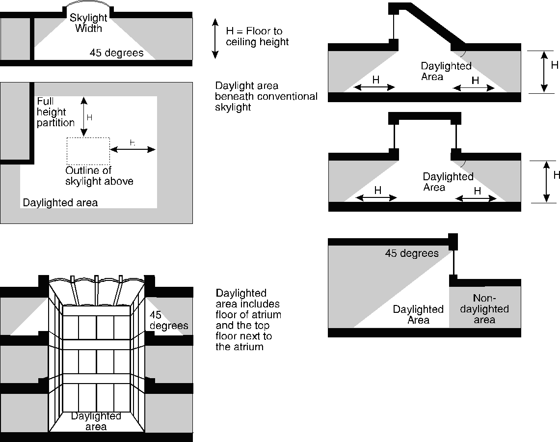
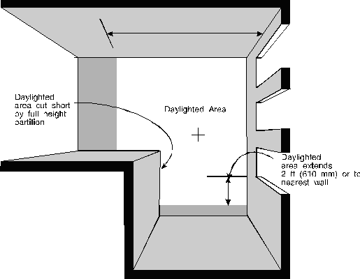