![[HOME]](/netaicon/homeicon.gif)
![[SEARCH]](/netaicon/srchpage.gif)

![[CURR_LIST]](/netaicon/curlist.gif)


![[BOTTOM]](/netaicon/bottom.gif)
![[HELP]](/netaicon/help.gif)
Seattle City Council Bills and Ordinances
Information modified on July 28, 2016; retrieved on June 6, 2026 9:06 PM
Ordinance 124275
Introduced as Council Bill 117872
Title | |
|---|---|
Description and Background | |
|---|---|
| Current Status: | Passed |
| Fiscal Note: | Fiscal Note to Council Bill No. 117872 |
| Index Terms: | MECHANICAL-CODES, PERMITS, FEES, ADMINISTRATIVE-PROCEDURES |
| References: | |
Legislative History | |
|---|---|
| Sponsor: | O'BRIEN |
| Date Introduced: | August 5, 2013 |
| Committee Referral: | Energy and Environment |
| Committee Action Date: | September 10, 2013 |
| Committee Recommendation: | Pass |
| Committee Vote: | 3(O'Brien, Burgess, Clark)-0 |
| City Council Action Date: | September 16, 2013 |
| City Council Action: | Passed |
| City Council Vote: | 9-0 |
| Date Delivered to Mayor: | September 20, 2013 |
|
Date Signed by Mayor: (About the signature date) | September 25, 2013 |
| Date Filed with Clerk: | September 26, 2013 |
| Signed Copy: | PDF scan of Ordinance No. 124275 |
Text | |||
|---|---|---|---|
|
AN ORDINANCE relating to the Seattle Mechanical Code, amending Chapter 22.400.010 of the Seattle Municipal Code, and adopting by reference Chapters 2 through 9, and Chapters 11 through 15 of the 2012 International Mechanical Code, and amending certain of those chapters; adopting a new Chapter 1 related to administration, permitting and enforcement; and repealing Sections 2-13 of Ordinance 123380. BE IT ORDAINED BY THE CITY OF SEATTLE AS FOLLOWS: Section 1. Section 22.400.010 of the Seattle Municipal Code is amended as follows:
22.400.010 Adoption of International Mechanical Code((
The Seattle Mechanical Code consists of: 1) the following portions of the (( Section 2. Chapter 1 of the Seattle Mechanical Code is adopted to read as follows: CHAPTER 1 ADMINISTRATION SECTION 101 TITLE 101.1 Title. These regulations shall be known as the "Seattle Mechanical Code," may be cited as such, and are referred to herein as "this code." All references to the International Mechanical Code contained in this code mean the Seattle Mechanical Code. SECTION 102 PURPOSE 102.1 Purpose. The purpose of this code is to provide minimum standards to safeguard life or limb, health, property and public welfare by regulating and controlling the design, construction, installation, quality of materials, location, operation, and maintenance or use of heating, ventilating, cooling, refrigeration systems, incinerators and other miscellaneous heat-producing appliances within the City. The purpose of this code is to provide for and promote the health, safety and welfare of the general public, and not to create or otherwise establish or designate any particular class or group of persons who will or should be especially protected or benefited by the terms of this code. SECTION 103 APPLICABILITY AND SCOPE 103.1 Scope. The provisions of this code apply to the erection, installation, alteration, repair, relocation, replacement, addition to, use or maintenance of any heating, ventilating, cooling, refrigeration systems, incinerators or other miscellaneous heat-producing appliances within the City. The design and testing of equipment regulated by this code are subject to the approval of the code official. Exceptions: 1. Detached oneand two-family dwellings and multiple singlefamily dwellings (townhouses) not more than three stories above grade plane with a separate means of egress and their accessory structures shall comply with the International Residential Code. 2. The standards for liquefied petroleum gas installations are the 2011 edition of NFPA 58 (Liquefied Petroleum Gas Code) and the 2012 edition of ANSI Z223.1/NFPA 54 (National Fuel Gas Code), as amended. 103.2 Applicability of city laws. A mechanical permit application shall be considered under the Seattle Mechanical, Fuel Gas and Energy codes in effect on a date as provided below, or on a date as otherwise required by law. 1. Mechanical permit applications shall be considered under the codes in effect on the date used to determine the codes applicable to the building permit application according to Seattle Building Code Section 101.3 if any of Items 1.1 through 1.3 apply: 1.1 The mechanical permit application is submitted as part of a building permit application; 1.2 The mechanical permit application is for work directly associated with a building permit but is submitted separately from the building permit application; or 1.3 The mechanical permit application is for initial tenant alterations submitted no later than 18 months after the date of the approved final inspection for the building, and is submitted before the expiration date of the building permit for the tenant alteration, as determined by Seattle Building Code Section 106.9. 2. Mechanical permit applications other than those subject to Item 1 shall be considered under the codes in effect on the date a complete mechanical permit application is submitted that complies with all the requirements of Section 116. 103.3 Additions, alterations and repairs. Additions, alterations, repairs and replacement of equipment or systems shall comply with the provisions for new equipment and systems except as otherwise provided in Section 104 of this code. Exception: Additions, alterations, renovations or repairs to a mechanical system that is part of a building addition with less than 500 square feet of conditioned floor area are exempt from the requirements for whole house ventilation systems, Section 403.8.5. 103.4 Internal consistency. Where, in any specific case, different sections of this code specify different materials, methods of construction or other requirements, the most restrictive governs. Where there is a conflict between a general requirement and a specific requirement, the specific requirement is applicable. 103.5 Referenced codes and standards. The codes and standards referenced in this code are part of the requirements of this code to the extent prescribed by each such reference. Where differences occur between provisions of this code and referenced codes and standards, the provisions of this code apply. Exception: Where enforcement of a code provision would violate the conditions of the listing of the equipment or appliance, the conditions of the listing and manufacturer's instructions apply. 103.6 Appendices. Provisions in the International Mechanical Code appendices do not apply unless specifically adopted. 103.7 Metric units. Wherever in this ordinance there is a conflict between metric units of measurement and English units, the English units govern. 103.8 References to other codes. Whenever an International, National or Uniform Code is referenced in this code, it means the Seattle edition of that code, including local amendments. References to the "Building Code", "Fuel Gas Code", "Fire Code", "Residential Code" and "Plumbing Code" mean the Seattle editions of those codes. SECTION 104 APPLICATION TO EXISTING MECHANICAL SYSTEMS 104.1 Additions, alterations or repairs. Additions, alterations, renovations or repairs may be made to any mechanical system without requiring the existing mechanical system to comply with all the requirements of this code, if the addition, alteration, renovation or repair conforms to the standards required for a new mechanical system. Additions, alterations, renovations or repairs shall not cause an existing system to become unsafe, unhealthy or overloaded. Minor additions, alterations, renovations, and repairs to existing mechanical systems may be installed in accordance with the law in effect at the time the original installation was made, if approved by the code official. 104.2 Existing installations. Mechanical systems lawful at the time of the adoption of this code may continue their use, be maintained or repaired, be converted to another type of fuel, or have components replaced if the use, maintenance, repair, conversion of fuel, or component replacement is done in accordance with the basic original design and location, and no hazard to life, health or property has been or is created by such mechanical system. 104.3 Changes in building occupancy. Mechanical systems that are a part of a building or structure undergoing a change in use or occupancy as defined in the Building Code shall comply with all requirements of this code that are applicable to the new use or occupancy. 104.4 Maintenance. All mechanical systems, materials, equipment, appurtenances and all parts thereof shall be maintained in proper operating condition in accordance with the original design and in a safe and hazard-free condition. All devices or safeguards that were required by a code in effect when the mechanical system was installed shall be maintained in conformance with the code edition under which installed. The owner or the owner's designated agent is responsible for maintenance of mechanical systems and equipment. To determine compliance with this subsection, the code official may cause a mechanical system or equipment to be reinspected. The fire chief and the code official each have authority to obtain compliance with the requirements of this subsection. Exception: The code official may modify the requirements of this section where all or a portion of the building is unoccupied. 104.5 Moved buildings. Building or structures moved into or within the City shall comply with standards adopted by the code official. No building shall be moved into or within the City unless, prior to moving, the code official has inspected the building for compliance with this code and the permit holder has agreed to correct all deficiencies found and has been issued a building permit for the work. A bond or cash deposit in an amount sufficient to abate or demolish the building shall be posted prior to issuance of a permit. See Section 116 for information required on plans. Any moved building that is not in complete compliance with standards for moved buildings within eighteen months from the date of permit issuance and is found to be a public nuisance may be abated. 104.6 Historic buildings and structures. The code official may modify the specific requirements of this code as it applies to landmarks and require in lieu thereof alternate requirements that, in the opinion of the code official, will result in a reasonable degree of safety to the public and the occupants of those buildings. For purposes of this section a landmark is a building or structure that has been nominated for designation or has been designated for preservation by the City Landmarks Preservation Board, or that has been designated for preservation by the State of Washington, or has been listed or determined eligible to be listed in the National Register of Historic Places, or is a structure in a landmark or special review district subject to a requirement to obtain a certificate of approval before making a change to the external appearance of the structure. SECTION 105 ALTERNATE MATERIALS AND METHODS OF CONSTRUCTION 105.1 Alternate materials and methods. This code does not prevent the use of any material, design or method of construction not specifically allowed or prohibited by this code, provided the alternate has been approved and its use authorized by the code official. The code official may approve an alternate, provided the code official finds that the proposed alternate complies with the provisions of this code and that the alternate, when considered together with other safety features of the building or other relevant circumstances, will provide at least an equivalent level of strength, effectiveness, fire resistance, durability, safety and sanitation. The code official may require that sufficient evidence or proof be submitted to reasonably substantiate any claims regarding the use or suitability of the alternate. The code official may, but is not required to, record the approval of alternates and any relevant information in the files of the code official or on the approved construction documents. SECTION 106 MODIFICATIONS 106.1 Modifications. The code official may modify the provisions of this code for individual cases if the code official finds: (1) there are practical difficulties involved in carrying out the provisions of this code; (2) the modification is in conformity with the intent and purpose of this code; and (3) the modification will provide a reasonable level of strength, effectiveness, fire resistance, durability, safety and sanitation when considered together with other safety features of the building or other relevant circumstances. The code official may, but is not required to, record the approval of modifications and any relevant information in the files of the code official or on the approved construction documents. SECTION 107 TESTS 107.1 Tests. Whenever there is insufficient evidence of compliance with the provisions of this code or evidence that any material or method of construction does not conform to the requirements of this code, the code official may require tests as proof of compliance, to be made at no expense to the City. Test methods shall be as specified in this code or by other recognized test standards. If there are no recognized and accepted test methods for the proposed alternate, the code official shall determine the test procedures. All tests shall be made by an approved agency. Reports of such tests shall be retained by the code official for the period required for retention of public records. SECTION 108 ORGANIZATION AND DUTIES OF CODE OFFICIAL 108.1 Jurisdiction of the Department of Planning and Development. The Department of Planning and Development is authorized to administer and enforce this code. The Department of Planning and Development is under the administrative and operational control of the Director, who is the code official. 108.2 Designees. The code official may appoint such officers, inspectors, assistants and employees as are authorized from time to time. The code official may authorize such employees and other agents as may be necessary to carry out the functions of the code official. 108.3 Right of entry. With the consent of the owner or occupier of a building or premises, or pursuant to a lawfully issued warrant, the code official may enter a building or premises at any reasonable time to perform the duties imposed by this code. 108.4 Liability. Nothing in this code is intended to be nor shall be construed to create or form the basis for any liability on the part of the City, or its officers, employees or agents, for any injury or damage resulting from the failure of equipment to conform to the provisions of this code, or by reason or as a consequence of any inspection, notice, order, certificate, permission or approval authorized or issued or done in connection with the implementation or enforcement of this code, or by reason of any action or inaction on the part of the City related in any manner to the enforcement of this code by its officers, employees or agents. This code shall not be construed to lessen or relieve the responsibility of any person owning, operating or controlling any equipment, building or structure for any damages to persons or property caused by defects, nor shall the Department of Planning and Development or the City of Seattle be held to have assumed any such liability by reason of the inspections authorized by this code or any permits or certificates issued under this code. 108.5 Cooperation of other officials and officers. The code official may request, and shall receive so far as is required in the discharge of the code official's duties, the assistance and cooperation of other officials of the City of Seattle. 108.6 Responsibility for compliance. Compliance with the requirements of this code is the obligation of the owner of the building, structure or premises, the duly authorized agent of the owner, and other persons responsible for the condition or work, and not of the City or any of its officers, employees or agents. SECTION 109 UNSAFE EQUIPMENT AND HAZARD CORRECTION ORDER 109.1 Unsafe equipment. Any equipment regulated by this code that is found to be unsafe is hereby declared to be a public nuisance and may be abated. 109.2 Emergency order . Whenever the code official finds that any equipment regulated by this code is in such a dangerous and unsafe condition as to constitute an imminent hazard to life or limb, the code official may issue an emergency order directing that the equipment be restored to a safe condition by a date certain. The order may also require that the building, structure or premises, or portion thereof, containing the equipment be vacated within a reasonable time to be specified in the order. In the case of extreme danger, the order may specify immediate vacation of the building, structure or premises, or may authorize immediate disconnection of the utilities or energy source. 109.2.1 Service of emergency order. The order shall be posted on the premises or personally served on the owner of the building or premises or any person responsible for the condition. The order shall specify the time for compliance. 109.2.2 Effect of emergency order. No person may occupy a building, structure or premises, or portion thereof, after the date on which the building is required to be vacated until the building, structure or premises, or portion thereof, is restored to a safe condition as required by the order and this code. It is a violation for any person to fail to comply with an emergency order issued by the code official. 109.3 Hazard correction order. Whenever the code official finds that unsafe equipment exists, the code official may issue a hazard correction order specifying the conditions causing the equipment to be unsafe and directing the owner or other person responsible for the unsafe equipment to correct the condition by a date certain. In lieu of correction, the owner may submit a report or analysis to the code official analyzing said conditions and establishing that the equipment is, in fact, safe. The code official may require that the report or analysis be prepared by a licensed engineer. 109.3.1 Service of hazard correction order. The order shall be posted on the premises or served on the owner of the building or premises or any person responsible for the condition by certified mail with return receipt requested. The order shall specify the time for compliance. 109.3.2 Effect of hazard correction order. It is a violation for any person to fail to comply with a hazard correction order as specified in this subsection. SECTION 110 ADMINISTRATIVE REVIEW 110.1 Administrative review by the code official. Applicants may request administrative review by the code official of decisions or actions pertaining to the administration and enforcement of this code. Requests shall be addressed to the code official. 110.2 Administrative review by the Construction Codes Advisory Board. Applicants may request review of decisions or actions pertaining to the application and interpretation of this code by the Construction Codes Advisory Board according to International Building Code Section 103.11, except for stop work orders, notices of violations and revocations of permits. The review will be performed by three or more members of the Construction Codes Advisory Board, chosen by the Board Chair. The Chair shall consider the subject of the review and members' expertise when selecting members to conduct a review. The decision of the review panel is advisory only; the final decision is made by the code official. SECTION 111 ENFORCEMENT, VIOLATIONS AND PENALTIES 111.1 Violations. It is a violation of this code for any person to: 1. Install, erect, construct, enlarge, alter, repair, replace, remodel, move, improve, remove, convert or demolish, equip, occupy, use or maintain any mechanical system or equipment or cause or permit the same to be done in the City, contrary to or in violation of any of the provisions of this code. 2. Use any material or install any device, appliance or equipment that is subject to this code and has not been approved by the code official. 3. Knowingly aid, abet, counsel, encourage, hire, induce or otherwise procure another to violate or fail to comply with this code. 4. Violate or fail to comply with any final order issued by the code official pursuant to the provisions of this code. 5. Remove, mutilate, destroy or conceal any notice or order issued or posted by the code official pursuant to the provisions of this code, or any notice or order issued or posted by the code official in response to a natural disaster or other emergency. 6. Conduct work under a permit without requesting an inspection as required by Section 119. 111.2 Notice of violation. If, after investigation, the code official determines that standards or requirements of this code have been violated or that orders or requirements have not been complied with, the code official may serve a notice of violation upon the owner, agent, or other person responsible for the action or condition. The notice of violation shall state the standards or requirements violated, shall state what corrective action, if any, is necessary to comply with the standards or requirements, and shall set a reasonable time for compliance. 111.2.1 Service of notice of violation. The notice shall be served upon the owner, agent or other responsible person by personal service or regular first class mail addressed to the last known address of such person, or if no address is available after reasonable inquiry, the notice may be posted in a conspicuous place on the premises. The notice may also be posted if served by personal service or first class mail. Nothing in this section limits or precludes any action or proceeding to enforce this code, and nothing obligates or requires the code official to issue a notice of violation prior to the imposition of civil or criminal penalties. 111.2.2 Review of notice of violation by the code official. Any person affected by a notice of violation issued pursuant to Section 111.2 may obtain a review of the notice by making a request in writing within ten days after service of the notice. When the last day of the period computed is a Saturday, Sunday, or city holiday, the period runs until 5 p.m. Of the next business day. 111.2.2.1 Review procedure. The review shall occur not less than ten nor more than 20 days after the request is received by the code official unless otherwise agreed to by the person requesting the review. Any person affected by the notice of violation may submit additional information to the code official. The review shall be made by a representative of the code official who will review any additional information that is submitted and the basis for issuance of the notice of violation. The reviewer may request clarification of the information received and a site visit. 111.2.2.2 Decision. After the review, the code official shall: 1. Sustain the notice; 2. Withdraw the notice; 3. Continue the review to a date certain; or 4. Amend the notice. 111.2.2.3 Order. The code official shall issue an order containing the decision within 15 days of the date that the review is completed and shall cause the order to be mailed by regular first class mail to the persons requesting the review and the persons named on the notice of violation, addressed to their last known address. 111.3 Stop work orders. The code official may issue a stop work order whenever any work is being done contrary to the provisions of this code, or in the event of dangerous or unsafe conditions related to equipment or construction. The stop work order shall identify the violation and may prohibit work or other activity on the site. 111.3 .1 Service of stop work order. The code official may serve the stop work order by posting it in a conspicuous place at the site, if posting is physically possible. If posting is not physically possible, then the stop work order may be served in the manner set forth in Revised Code of Washington (RCW) 4.28.080 for service of a summons or by sending it by first class mail to the last known address of: the property owner, the person doing or causing the work to be done, or the holder of a permit if work is being stopped on a permit. For purposes of this section, service is complete at the time of posting or of personal service, or if mailed, three days after the date of mailing. When the last day of the period so computed is a Saturday, Sunday or city holiday, the period runs until 5 p.m. on the next business day. 111.3 .2 Effective date of stop work order. Stop work orders are effective when posted, or if posting is not physically possible, when one of the persons identified in Section 111.3.1 is served. 111.3 .3 Review of stop work orders by the code official. Any person aggrieved by a stop work order may obtain a review of the order by delivering to the code official a request in writing within two business days of the date of service of the stop work order. 111.3 .3.1 Review procedure. The review shall occur within two business days after receipt by the code official of the request for review unless otherwise agreed by the person making the request. Any person affected by the stop work order may submit additional information to the code official for consideration as part of the review at any time prior to the review. The review will be made by a representative of the code official who will review all additional information received and may also request a site visit. 111.3 .3.2 Decision. After the review, the code official may: 1. Sustain the stop work order; 2. Withdraw the stop work order; 3. Modify the stop work order; or 4. Continue the review to a date certain. 111.3 .3.3 Order. The code official shall issue an order of the code official containing the decision within two business days after the review is completed and shall cause the order to be sent by regular first class mail to the person or persons requesting the review, any person on whom the stop work order was served, and any other person who requested a copy before issuance of the order, addressed to their last known address. 111.4 Authority to disconnect utilities in emergencies. The code official has the authority to disconnect fuel-gas utility service or energy supplies to a building, structure, premises or equipment regulated by this code in case of emergency where necessary to eliminate an immediate hazard to life or property. The code official may enter any building or premises to disconnect utility service. The code official shall, whenever possible, notify the serving utility, the owner and the occupant of the building, structure or premises of the decision to disconnect prior to taking such action, and shall notify the serving utility, owner and occupant of the building, structure or premises in writing of such disconnection immediately thereafter. 111.5 Authority to condemn equipment. Whenever the code official determines that any equipment or portion thereof regulated by this code is hazardous to life, health or property, the code official shall order in writing that such equipment either be disconnected, removed or restored to a safe or sanitary condition, as appropriate. The written notice shall fix a date certain for compliance with such order. It is a violation for any person to use or maintain defective equipment after receiving such notice. When any equipment or installation is to be disconnected, the code official shall give written notice of such disconnection and causes therefore within 24 hours to the serving utility, the owner and the occupant of the building, structure or premises. When any equipment is maintained in violation of this code, and in violation of a notice issued pursuant to the provisions of this section, the code official shall institute any appropriate action to prevent, restrain, correct or abate the violation. 111.6 Connection after order to disconnect. No person shall make connections from any energy, fuel or power supply nor supply energy or fuel to any equipment regulated by this code that has been disconnected or ordered to be disconnected by the code official, or the use of which has been ordered to be discontinued by the code official until the code official authorizes the reconnection and use of such equipment. 111.7 Civil penalties . Any person violating or failing to comply with the provisions of this code is subject to a cumulative civil penalty in an amount not to exceed $500 per day for each violation from the date the violation occurs or begins until compliance is achieved. In cases where the code official has issued a notice of violation, the violation will be deemed to begin, for purposes of determining the number of days of violation, on the date compliance is required by the notice of violation. 111.8 Enforcement in Municipal Court. Civil actions to enforce this chapter shall be brought exclusively in Seattle Municipal Court, except as otherwise required by law or court rule. In any civil action for a penalty, the City has the burden of proving by a preponderance of the evidence that a violation exists or existed; the issuance of a notice of violation or of an order following a review by the code official is not itself evidence that a violation exists. 111.9 Judicial review. Because civil actions to enforce this code must be brought exclusively in Seattle Municipal Court pursuant to Section 111.8, orders of the code official, including notices of violation issued under this chapter, are not subject to judicial review pursuant to chapter 36.70C RCW. 111.10 Alternative criminal penalty. Anyone who violates or fails to comply with any notice of violation or order issued by the code official pursuant to this code or who removes, mutilates, destroys or conceals a notice issued or posted by the code official shall, upon conviction thereof, be punished by a fine of not more than $5000 or by imprisonment for not more than 365 days, or by both such fine and imprisonment for each separate violation. Each day's violation shall constitute a separate offense. 111.11 Additional relief. The code official may seek legal or equitable relief to enjoin any acts or practices and abate any condition when necessary to achieve compliance. SECTION 112 RECORDING OF ORDERS AND NOTICES 112.1 Recording. The code official may record a copy of any order or notice with the Department of Records and Elections of King County. SECTION 113 RULES OF THE CODE OFFICIAL 113.1 Authority. The code official has authority to issue interpretations of this code and to adopt and enforce rules and regulations supplemental to this code as may be deemed necessary to clarify the application of the provisions of this code. Such interpretations, rules and regulations shall be in conformity with the intent and purpose of this code. 113.2 Procedure for adoption of rules. The code official shall promulgate, adopt and issue rules according to the procedures specified in the Administrative Code, Chapter 3.02 of the Seattle Municipal Code. SECTION 114 CONSTRUCTION CODES ADVISORY BOARD 114.1 CCAB committee. A committee of the Construction Codes Advisory Board may examine proposed administrative rules, appeals and amendments relating to this code and related provisions of other codes and make recommendations to the code official and to the City Council for changes in this code. The committee will be called on as needed by the Construction Codes Advisory Board. SECTION 115 PERMITS 115.1 Permits required. Except as otherwise specifically provided in this code, a permit shall be obtained from the code official prior to each installation, alteration, repair, replacement or remodel of any equipment or mechanical system regulated by this code. A separate mechanical permit is required for each separate building or structure. 115.2 Work exempt from permit. 115.2.1 Mechanical. A mechanical permit is not required for the work listed below. 1. Any portable heating appliance, portable ventilating equipment, or portable cooling unit, if the total capacity of these portable appliances does not exceed 40 percent of the cumulative heating, cooling or ventilating requirements of a building or dwelling unit and does not exceed 3 kW or 10,000 Btu input. 2. Any closed system of steam, hot or chilled water piping within heating or cooling equipment regulated by this code. 3. Minor work or the replacement of any component part of a mechanical system that does not alter its original approval and complies with other applicable requirements of this code. 115.2.2 Refrigeration. A mechanical permit is not required for the following refrigerant equipment: 1. Any self-contained refrigerating equipment for which an operating permit is not required. 2. Any self-contained refrigeration system that does not exceed three horsepower rating. 115.3 Compliance required. All work shall comply with this code, even where no permit is required. 115.4 Flood hazard areas. In addition to the permit required by this section, all work to be performed in areas of special flood hazard as defined in Chapter 25.06 of the Seattle Municipal Code, subject to additional standards and requirements set forth in Chapter 25.06, the Seattle Floodplain Development Ordinance. 115.5 Emergency repairs. In the case of an emergency, the installation, alteration or repair of any refrigeration system or equipment may be made without a permit, provided that application for a permit is made within the later of 24 hours or one working day from the time when the emergency work was started. SECTION 116 APPLICATION FOR PERMIT 116.1 Application. To obtain a permit, the applicant shall first file an application in writing on a form furnished by the code official or in another format determined by the code official. Every such application shall: 1. Identify and describe the work to be covered by the permit for which application is made. 2. Describe the land on which the proposed work is to be done by legal description, property address or similar description that will readily identify and definitely locate the proposed building or work. 3. Provide the contractor's business name, address, phone number and current contractor registration number (required if contractor has been selected). To obtain a permit for work on a refrigeration system, the applicant shall also provide the number of the refrigeration contractor license issued by the City. 4. Be accompanied by construction documents, including plans, diagrams, computations and specifications, equipment schedules and other data as required in Sections 116.2 and 116.3. 5. State the valuation of the mechanical work to be done. The valuation of the mechanical work is the estimated current value of all labor and material, whether actually paid for or not, for which the permit is sought. 6. Be signed by the owner of the property or building, or the owner's authorized agent, who may be required to submit evidence to indicate such authority. 7. Give such other data and information as may be required by the code official. 8. Indicate the name of the owner and contractor and the name, address and phone number of a contact person. 116.2 Construction documents. Construction documents shall be submitted in one or more sets with each application for a permit, or shall be submitted in electronic format determined by the code official. The code official may require plans, computations and specifications to be prepared and designed by an engineer or architect licensed by the state to practice as such. Projects having a total mechanical valuation of $50,000 or larger shall have a mechanical engineering stamp and signature on each sheet. Exception: A mechanical engineer's stamp or submission of construction documents is not required if the code official finds that the nature of the work applied for is such that review of construction documents is not necessary to obtain compliance with this code. 116.3 Information on construction documents. 116.3.1 Clarity of plans. Plans shall be drawn to a clearly indicated and commonly accepted scale upon substantial paper such as blueprint quality or standard drafting paper. Tissue paper, posterboard or cardboard will not be accepted. The plans shall be of microfilm quality and limited to a minimum size of 18 inches by 18 inches and a maximum size of 41 inches by 54 inches. Plans and specifications shall be of sufficient clarity to show that the proposed installation will conform to the provisions of this code and to the provisions of all applicable laws, ordinances, rules, regulations and orders. Plans may be submitted in electronic format as determined by the code official. 116.3.2 Fire-resistive notes. The code official may require that plans for buildings more than two stories in height of other than Group R-3 and Group U occupancies indicate how required structural and fire-resistive integrity will be maintained where a penetration will be made for electrical, mechanical, plumbing and communication conduits, pipes and similar systems. 116.3.3 Information required on plans. The plans or specifications shall show the following: 1. Layout for each floor with dimensions of all working spaces and a legend of all symbols used. 2. Location, size and material of all piping. 3. Location, size and materials of all air ducts, air inlets and air outlets. 4. Location of all fans, warm-air furnaces, boilers, absorption units, refrigerant compressors and condensers and the weight of all pieces of such equipment weighing 200 pounds or more. 5. Rated capacity or horsepower and efficiency rating of all boilers, warm-air furnaces, heat exchangers, blower fans, refrigerant compressors and absorption units. See also the International Energy Conservation Code. 6. Location, size and material of all combustion products vents and chimneys. 7. Location and area of all ventilation and combustion air openings and ducts. 8. Location of all air dampers and fire shutters. 9. The first sheet of each set of plans and specifications shall show the address of the proposed work and the name and address of the owner or lessee of the premises. 10. Architectural drawings, typical envelope cross sections and other drawings or data may be required to support system sizing calculations or other thermal requirements of this code or the International Energy Conservation Code. SECTION 117 APPLICATION REVIEW AND PERMIT ISSUANCE 117.1 Issuance. The application and, construction documents shall be reviewed by the code official. The construction documents may be reviewed by other departments of the City to check compliance with the laws and ordinances under their jurisdiction. 117.1.1 Decision and issuance of permit. If the code official finds that the work as described in an application for a permit and the construction documents substantially conform to the requirements of this code and other pertinent laws and ordinances and that the fees specified in the Seattle Municipal Code, Title 22, Subtitle IX, Permit Fees have been paid, the code official shall issue a permit to the applicant. When the permit is issued, the applicant or the applicant's authorized agent becomes the permit holder. 117.1.2 Compliance with approved plans and permit. When the code official issues a permit, the code official shall endorse the permit in writing or in electronic format and stamp the plans "APPROVED." Such approved plans and permit shall not be changed, modified or altered without authorization from the code official, and all work shall be done in accordance with the approved construction documents and permit except as the code official may require during field inspection to correct errors or omissions. 117.2 Revisions to the permit. When changes to the approved work are made during construction, approval of the code official shall be obtained prior to execution. The building or mechanical inspector may approve minor changes for work not reducing the structural strength or fire and life safety of the structure. The building or mechanical inspector shall determine if it is necessary to revise the approved construction documents. If revised plans are required, changes shall be shown on two sets of plans that shall be submitted to and approved by the code official, accompanied by appropriate fees as specified in the Seattle Municipal Code, Title 22, Subtitle IX, Permit Fees prior to occupancy. All changes shall conform to the requirements of this code and other pertinent laws and ordinances and other issued permits. Minor changes shall not incur additional fees if these changes do not (1) add to the general scope of work; (2) change the basic design concept; (3) involve major relocation of equipment, ducts, or pipes; (4) substantially alter approved equipment size; or (5) require extensive re-review of the plans and specifications. 117.3 Cancellation of permit applications. Applications may be cancelled if no permit is issued by the earlier of the following: (1) twelve months following the date of application; or (2) sixty days after the date of written notice that the permit is ready to be issued. After cancellation, construction documents may be returned to the applicant or destroyed by the code official. The code official shall notify the applicant in writing at least 30 days before the application is cancelled. The notice shall specify a date by which a request for extension must be submitted in order to avoid cancellation. The date shall be at least two weeks prior to the date on which the application will be cancelled. 117.4 Extensions prior to permit issuance. At the discretion of the code official, applications for projects that require more than 12 months to review and approve may be extended for a period that provides reasonable time to complete the review and approval, but in no case longer than 24 months from the date of the original application. No application may be extended more than once. After cancellation, the applicant shall submit a new application and pay a new fee to restart the application process. Notwithstanding other provisions of this code, applications may be extended where issuance of the permit is delayed by litigation, preparation of environmental impact statements, appeals, strikes or other causes related to the application that are beyond the applicant's control, or while the applicant is making progress toward issuance of a master use permit. 117.5 Retention of plans. One set of approved plans, which may be on microfilm or in electronic format, shall be retained by the code official. One set of approved plans shall be returned to the applicant and shall be kept at the site of the building or work for use by the inspection personnel at all times when the work authorized is in progress. 117.6 Validity of permit. The issuance or granting of a permit or approval of construction documents shall: 1. Not be construed to be a permit for, or an approval of, any violation of any of the provisions of this code or other pertinent laws and ordinances. 2. Not prevent the code official from requiring the correction of errors in the construction documents, or from preventing building operations being carried on thereunder when in violation of this code or of other pertinent laws and ordinances of the City. 3. Not prevent the code official from requiring correction of conditions found to be in violation of this code or other pertinent laws and ordinances of the City, or 4. Not be construed to extend the period of time for which any such permit is issued or otherwise affect any period of time for compliance specified in any notice or order issued by the code official or other administrative authority requiring the correction of any such conditions. 117.7 Permit expiration. Authority to do the work authorized by a permit expires 18 months from the date of issuance. An approved renewal extends the life of the permit for an additional 18 months from the prior expiration date. An approved reestablishment extends the life of the permit for 18 months from the date the permit expired. Exceptions: 1. Initial permits for major construction projects that require more than 18 months to complete may be issued for a period that provides reasonable time to complete the work, according to an approved construction schedule. The building official may authorize a permit expiration date not to exceed three years from the date of issuance.. 2. The code official may issue permits that expire in less than 18 months if the code official determines a shorter period is appropriate to complete the work. 117.8 Renewal of permits. Permits may be renewed and renewed permits may be further renewed by the code official, if the following conditions are met: 1. Application for renewal is made within the 30 day period immediately preceding the date of expiration of the permit; and 2. If the project has had an associated discretionary Land Use review, and the land use approval has not expired; and 3. If an application for renewal is made more than 18 months after the date of mandatory compliance with a new or revised edition of this code, the permit shall not be renewed unless: 3.1 The code official determines that the permit complies, or is modified to comply with the Seattle Mechanical, Fuel Gas and Energy codes in effect on the date of application for renewal; or 3.2 The work authorized by the permit is substantially underway and progressing at a rate approved by the building official. "Substantially underway" means that normally required inspections have been approved for work such as foundations, framing, mechanical, insulation and finish work is being completed on a continuing basis; or 3.3 Commencement or completion of the work authorized by the permit is delayed by litigation, appeals, strikes or other extraordinary circumstances related to the work authorized by the permit, beyond the permit holder's control, subject to approval by the code official. 117.9 Reestablishment of expired permits. A new permit is required to complete work if a permit has expired and was not renewed. Exception: A permit that expired less than one year prior to the date of a request for reestablishment may be reestablished upon approval of the code official if it complies with Items 2 and 3 of Section 117.8. Once re-established the permit will not be considered to have expired. The new expiration date of a re-established permit shall be determined in accordance with Section 117.7. 117.10 Revocation of mechanical permits. Whenever the code official determines there are grounds for revoking a permit, the code official may issue a notice of revocation. The notice of revocation shall identify the reason for the proposed revocation, including the violations, the conditions violated, and any alleged false or misleading information provided. 117.10.1 Standards for revocation. The code official may revoke a permit if: 1. The code or the permit has been or is being violated and issuance of a notice of violation or stop work order has been or would be ineffective to secure compliance because of circumstances related to the violation; or 2. The permit was obtained with false or misleading information. 117.10.2 Service of notice of revocation. The notice of revocation shall be served on the owner of the property on which the work is occurring, the holder of a permit if different than the owner, and the person doing or causing the work to be done. The notice of revocation shall be served in the manner set forth in RCW 4.28.080 for service of a summons or sent by first class mail to the last known address of the responsible party. For purposes of this section, service is complete at the time of personal service, or if mailed, three days after the date of mailing. When the last day of the period so computed is a Saturday, Sunday or city holiday, the period runs until 5 p.m. on the next business day. 117.10.3 Effective date of revocation. The code official shall identify in the notice of revocation a date certain on which the revocation will take effect. This date may be stayed pending complete review by the code official pursuant to Section 117.10.4. 117.10.4 Review by the code official for notice of revocation. Any person aggrieved by a notice of revocation may obtain a review by making a request in writing to the code official within three business days of the date of service of the notice of revocation. 117.10.4.1 Review procedure. The review will be made by a representative of the code official who will review all additional information received and may also request a site visit. After the review, the code official may: 1. Sustain the notice of revocation and affirm or modify the date the revocation will take effect; 2. Withdraw the notice of revocation; 3. Modify the notice of revocation and affirm or modify the date the revocation will take effect; or 4. Continue the review to a date certain. 117.10.4.2 Order of revocation of permit. The code official shall issue an order of the code official containing the decision within ten days after the review is completed and shall cause the same to be sent by regular first class mail to the person or persons requesting the review, any other person on whom the notice of revocation was served, and any other person who requested a copy before issuance of the order. SECTION 118 FEES 118.1 Fees. A fee for each mechanical permit and for other activities related to the enforcement of this code shall be paid as set forth in the Seattle Municipal Code, Title 22, Subtitle IX, Permit Fees. SECTION 119 INSPECTIONS 119.1 General. All construction or work for which a permit is required is subject to inspection by the code official, and certain types of construction shall have special inspections by registered special inspectors specified in Chapter 17 of the International Building Code. 119.2 Inspection requests. The owner of the property or the owner's authorized agent, or the person designated by the owner/agent to do the work authorized by a permit shall notify the code official that work requiring inspection as specified in this section and Section 120 is ready for inspection. 119.3 Access for inspection. The permit holder and the person requesting any inspections required by this code shall provide access to and means for proper inspection of such work, including safety equipment required by the Washington Industrial Safety and Health Agency. The work shall remain accessible and exposed for inspection purposes until approved by the code official. Neither the code official nor the City shall be liable for expense entailed in the required removal or replacement of any material to allow inspection. 119.4 Inspection record. Work requiring a mechanical permit shall not be commenced until the permit holder or the permit holder's agent has posted an inspection record in a conspicuous place on the premises and in a position that allows the code official to conveniently make the required entries regarding inspection of the work. This record shall be maintained in such a position by the permit holder or the permit holder's agent until final approval has been granted by the code official. 119.5 Approvals required. No work shall be done on any part of the building or structure beyond the point indicated in each successive inspection without first obtaining the written approval of the code official. Written approval shall be given only after an inspection has been made of each successive step in the construction as indicated by each of the inspections required in this code. 119.5.1 Effect of approval. Approval as a result of an inspection is not approval of any violation of the provisions of this code or of other pertinent laws and ordinances of the City. Inspections presuming to give authority to violate or cancel the provisions of this code or of other pertinent laws and ordinances of the City are not valid. 119.6 Final inspection. When the installation of a mechanical system is complete, an additional and final inspection shall be made. 119.7 Operation of mechanical equipment. The requirements of this section do not prohibit the operation of any mechanical systems installed to replace existing equipment or fixtures serving an occupied portion of the building in the event a request for inspection of such equipment or fixture has been filed with the code official not more than 48 hours after such replacement work is completed, and before any portion of such mechanical system is concealed by any permanent portion of the building. 119.8 Testing of equipment and systems. Refrigeration equipment regulated by this code shall be tested and approved as required by Chapter 11 of this code. Fuel-oil piping shall be tested and approved as required by Chapter 13 of this code. 119.9 Other inspections. In addition to the "called" inspections specified above, the code official may make or require any other inspections of any mechanical work to ascertain compliance with the provisions of this code and other laws and ordinances that are enforced by the code official. 119.10 Special investigation. If work for which a permit or approval is required is commenced or performed prior to making formal application and receiving the code official's permission to proceed, the code official may make a special investigation inspection before a permit is issued for the work. If a special investigation is made, a special investigation fee may be assessed in accordance with the Fee Subtitle. 119.11 Reinspections. The code official may require a reinspection if work for which inspection is called is not complete, corrections required are not made, the inspection record is not properly posted on the work site, the approved plans are not readily available to the inspector, access is not provided on the date for which inspection is requested, if deviations from construction documents that require the approval of the code official have been made without proper approval, or as otherwise required by the code official. 119.11.1 Compliance with Section 104.4. For the purpose of determining compliance with Section 104.4, Maintenance, the code official or the fire chief may cause any structure or system to be reinspected. 119.11.2 Reinspection fee. The code official may assess a reinspection fee as set forth in the Seattle Municipal Code, Title 22, Subtitle IX, Permit Fees for any action for which reinspection is required. In instances where reinspection fees have been assessed, no additional inspection of the work will be performed until the required fees have been paid. SECTION 120 CONNECTION APPROVAL 120.1 Energy connections. No person shall make connections from a source of energy fuel to a mechanical system or equipment regulated by this code for which a permit is required until approved by the code official. 120.2 Temporary connections. The code official may authorize temporary connection of the mechanical equipment to the source of energy fuel for the purpose of testing the equipment, or for use under a temporary certificate of occupancy. SECTION 121 REFRIGERATION LICENSES 121.1 Refrigeration licenses. No person shall perform any of the services or activities related to refrigeration systems regulated by Chapter 11 without a license required by Chapter 6.82 of the Seattle Municipal Code, or under the direct supervision of a person holding a required license. SECTION 122 OPERATING PERMITS FOR REFRIGERATION SYSTEMS 122.1 An operating permit issued by the code official is required to operate any refrigeration system meeting any one of the following criteria: 1. Any system over 50 horsepower, or 2. Any system over 50 tons of refrigerant effect, or 3. Any system that contains over 150 pounds of refrigerant, or 4. Any system that includes a refrigerant containing a pressure vessel over six inches in diameter with a capacity of more than 5 cubic feet and a design working pressure under 250 psig, or 5. Any system that includes a refrigerant containing a pressure vessel over six inches in diameter having a capacity of one and one-half cubic feet and a design working pressure over 250 psig. 122.2 The operating permit will not be issued until the system has been inspected and approved by the code official as safe to operate and in compliance with the provisions of this code. The permit is valid for a period of one year, renewable annually. The permit shall be displayed in a conspicuous place adjacent to the refrigeration system. Section 3. The following sections of Chapter 2 of the International Mechanical Code, 2012 Edition, are amended as follows: CHAPTER 2 DEFINITIONS SECTION 201 GENERAL ***
201.3 Terms defined in other codes. Where terms are not defined in this code and are defined in the International Building Code, International Fire Code, Seattle Electrical Code, International Fuel Gas Code or the (( *** SECTION 202 GENERAL DEFINITIONS ***
(( ***
BOILER. A closed heating appliance intended to supply hot water or steam for space heating, processing or power purposes. (( BOILER CODE. The Seattle Boiler and Pressure Vessel Code. ***
[A] CODE. These regulations, subsequent amendments thereto, or any emergency rule or regulation that ((
[A] CODE OFFICIAL. The (( ***
CONDITIONED SPACE. (( CONFINED SPACE. A space having a volume less than 50 cubic feet per 1,000 Btu per hour (Btu/h) (4.8 m 3 /kW) of the aggregate input rating of all appliances installed in that space. *** CONTAINER (REFRIGERANT). A cylinder for the transportation of refrigerant . *** DAMPER. A manually or automatically controlled device to regulate draft or the rate of flow of air or combustion gases. Backdraft damper. A damper installed to restrict introduction of unconditioned air from an unconditioned space to a conditioned space. Fire damper. See "fire damper". Smoke damper. See "smoke damper". Volume damper. A device that, when installed, will restrict, retard or direct the flow of air in a duct, or the products of combustion in a heat-producing appliance, its vent connector, vent or chimney therefrom. *** DIRECT REFRIGERATION SYSTEM. A system in which the evaporator or condenser of the refrigerating system is in direct contact with the air or other substances to be cooled or heated. See Figure 2-1. *** ENVIRONMENTAL AIR. Air that is , at temperatures not exceeding 250 0 F (121 0 C), conveyed to or from occupied areas through ducts which are not part of the heating or air-conditioning system, such as ventilation for human usage, relief air, domestic kitchen range exhaust, bathroom exhaust, domestic clothes dryer exhaust , transformer vault exhaust, elevator exhaust, and parking garage exhaust. *** EXIT PASSAGEWAY. An exit component that provides for a protected path of egress travel in a horizontal direction to an exit or to the exit discharge. *** [F] GAS ROOM. A separately ventilated, fully enclosed room in which only compressed gases and associated equipment and supplies are stored or used. *** [B] HIGH-RISE BUILDING. A building with an occupied floor located more than 75 feet (22 860 mm) above the lowest level of fire department vehicle access. *** HOOD. An air intake device used to capture by entrapment, impingement, adhesion or similar means, grease, moisture, heat and similar contaminants before they enter a duct system. Type I. A kitchen hood for collecting and removing grease vapors and smoke generated from medium-duty, heavy-duty, extra-heavy-duty, and some light-duty cooking appliances . Such hoods are equipped with a fire suppression system. Type II. A general kitchen hood for collecting and removing steam, vapor, heat, odors and products of combustion generated from some light-duty cooking appliances . *** INDIRECT REFRIGERATION SYSTEM. A system in which a secondary coolant cooled or heated by the refrigerating system is circulated to the air or other substance to be cooled or heated. See Figure 2-2. Indirect systems are distinguished by the method of application shown below: Closed system. A system in which a secondary fluid is either cooled or heated by the refrigerating system and then circulated within a closed circuit in indirect contact with the air or other substance to be cooled or heated. Double-indirect open-spray system. A system in which the secondary substance for an indirect open-spray system is heated or cooled by an intermediate coolant circulated from a second enclosure. Open-spray system. A system in which a secondary coolant is cooled or heated by the refrigerating system and then circulated in direct contact with the air or other substance to be cooled or heated. Vented closed system. A system in which a secondary coolant is cooled or heated by the refrigerating system and then passed through a closed circuit in the air or other substance to be cooled or heated, except that the evaporator or condenser is placed in an open or appropriately vented tank. INTERIOR EXIT STAIRWAY. An exit component that serves to meet one or more means of egress design requirements, such as required number of exits or exit access travel distance, and provides for a protected path of egress travel to the exit discharge or public way. *** LIGHT-DUTY COOKING APPLIANCE. Light-duty cooking appliances include gas and electric ovens of a maximum 6 kW or 20,000 Btu/h capacity (including standard, bake, roasting, revolving, retherm, convection, combination convection/steamer, countertop conveyorized baking/finishing, deck and pastry), electric and gas steam-jacketed kettles, electric and gas pasta cookers, electric and gas compartment steamers (both pressure and atmospheric) and electric and gas cheesemelters. *** [W] LOCAL EXHAUST. An exhaust system that uses one or more fans to exhaust air from a specific room or rooms within a dwelling. ***
MEDIUM-DUTY COOKING APPLIANCE. Medium-duty cooking appliances include electric discrete element ranges (with or without oven), electric and gas hot-top ranges, electric and gas griddles, electric and gas double-sided griddles, electric and gas fryers
(including open deep fat fryers, donut fryers, kettle fryers and pressure fryers), (( *** PERSON. Any individual, receiver, administrator, executor, assignee, trustee in bankruptcy, trust, estate, firm, partnership, joint venture, club, company, joint stock company, business trust, municipal corporation, political subdivision of the State of Washington, corporation, limited liability company, association, society or any group of individuals acting as a unit, whether mutual, cooperative, fraternal, nonprofit or otherwise, and the United States or any instrumentality thereof. ***
(( ***
(( *** Product-conveying . Conveying solid particulates, such as refuse, dust, fumes and smoke; liquid particulate matter, such as spray residue, mists and fogs; vapors, such as vapors from flammable or corrosive liquids; noxious and toxic gases; and air at temperatures exceeding 250 degrees F (121 degrees C). Examples include, but are not limited to, combustion engine, industrial vacuum system, chemical booth, paint booth, paint enclosure and photo lab exhaust. *** RELIEF AIR. Exhausted return air from a system that provides ventilation for human usage. ***
(( *** THIMBLE. A listed fitting designed to be installed in the opening in a masonry chimney through which the chimney connector passes. *** UNCONFINED SPACE. A space having a volume not less than 50 cubic feet per 1,000 Btu/h (4.8m 3 /kW) of the aggregate input rating of all fuel-burning appliances installed in that space. Rooms communicating directly with the space in which the appliances are installed, through openings not furnished with doors, are considered a part of the unconfined space. *** UNSAFE. Constituting a fire or health hazard or otherwise dangerous to human life, constituting a hazard to safety, health or public welfare. *** WATER HEATER. Any heating appliance or equipment , not exceeding a pressure of 160 psi (1103 kPa), a volume of 120 gallons and a heat input of 200,000 Btu/hr, that heats potable water and supplies such water to the potable hot water distribution system. [W] WHOLE HOUSE VENTILATION SYSTEM. A mechanical ventilation system, including fans, controls, and ducts, which replaces, by direct or indirect means, air from the habitable rooms with outdoor air. *** Section 4. The following sections of Chapter 3 of the International Mechanical Code, 2012 Edition, are amended as follows: CHAPTER 3 GENERAL REGULATIONS SECTION 301 GENERAL ***
301.1 Scope. This chapter shall govern the approval and installation of all equipment and appliances that comprise parts of the building mechanical systems regulated by this code in accordance with Section (( *** 301.3 Identification. Each length of pipe and tubing and each pipe fitting utilized in a mechanical system shall bear the identification of the manufacturer. [W] Exception: The manufacturer identification for fittings and pipe nipples shall be on each piece or shall be printed on the fitting or nipple packaging or provided documentation. *** 301.7 Listed and labeled. Appliances regulated by this code shall be listed and labeled for the application in which they are installed and used, unless otherwise approved in accordance with Section 105 or 106 . Exception: Listing and labeling of equipment and appliances used for refrigeration shall be in accordance with Section 1101.2. ***
301.10 Electrical. Electrical wiring, controls and connections to equipment and appliances regulated by this code shall be in accordance with ((
301.11 Plumbing connections. Potable water supply and building drainage system connections to equipment and appliances regulated by this code shall be in accordance with the (( *** SECTION 303 EQUIPMENT AND APPLIANCE LOCATION *** 303.7 Pit locations. Appliances installed in pits or excavations shall not come in direct contact with the surrounding soil. The sides of the pit or excavation shall be held back a minimum of 12 inches (305 mm) from the appliance , and a minimum of 30 inches (762 mm) on the control side . Where the depth exceeds 12 inches (305 mm) below adjoining grade, the walls of the pit or excavation shall be lined with concrete or masonry. Such concrete or masonry shall extend a minimum of 4 inches (102 mm) above adjoining grade and shall have sufficient lateral load-bearing capacity to resist collapse. The appliance shall be protected from flooding in an approved manner.
[B] 303.8 (( Installation of pipes or ducts conveying gases, vapors or liquids in hoistways, machine rooms, or machinery spaces for elevators. Pipes and ducts conveying gases, vapors or liquids shall not be installed in elevator hoistways, elevator machine rooms, and elevator machinery spaces. Exceptions: 1. Only ducts for heating, cooling, ventilating, and venting these spaces are permitted to be installed in the hoistway, machine room, and machinery space. 2. Ducts and electrical conduit may pass through an elevator machine room or machinery space if they are separated from the room or space by construction equal to the rated construction of the room or space and located so that all required clearances are maintained. If a vented machine room is not vented directly to the outside of the building, the vent shall be enclosed within a fire barrier with at least a one-hour fire-resistance rating, or as required for a shaft where it passes through occupied floors. 3. Standard sprinkler protection conforming to the requirements of NFPA 13 is permitted to be installed in these spaces, subject to rules promulgated by the code official. 4. Subject to the approval of the code official, pipes that are protected with double containment whose joints are threaded, soldered or welded joints are permitted. Pipes shall not be located less than 7 feet above the floor in machine rooms. [B] 303.9 Interior exit stairways and exit passageways. Mechanical systems shall not be located in interior exit stairways and ramps and exit passageways. Penetrations into and openings through interior exit stairways and ramps and exit passageways are prohibited except for: 1. Equipment allowed or required by the International Building Code to serve the interior exit stairway and exit passageways such as: 1.1 Ductwork and equipment necessary for independent ventilation or stairway pressurization, 1.2 Sprinkler piping, 1.3 Standpipes, 1.4 Electrical raceway serving the interior exit stairway or ramp terminating in a steel box not exceeding 16 square inches (10 323 mm 2 ) in area, and 1.5 Piping used exclusively for the drainage of rainfall runoff from roof areas provided the roof is not used for a helistop or heliport. 2. Unfired heaters allowed by the International Building Code for freeze protection of fire protection equipment may penetrate one protective membrane. The conduit serving the heater may penetrate both protective membranes. Such penetrations shall be protected in accordance with International Building Code Section 714. There shall be no penetrations or communicating openings, whether protected or not, between adjacent interior exit stairways and ramps. Exception: Membrane penetrations shall be permitted on the outside of the interior exit stairway and ramp. Such penetrations shall be protected in accordance with International Building Code Section 714.3.2. Interpretation: Ducts passing through interior exit stairways shall be separated from the stairway by construction having a fire-resistance rating at least equal to the stairway walls. At least one side of the duct enclosure shall abut the interior exit stairway enclosure. SECTION 304 INSTALLATION *** 304.3 Elevation of ignition source. Equipment and appliances having an ignition source and located in hazardous locations and public garages, private garages, repair garages, automotive motor fuel-dispensing facilities and parking garages shall be elevated such that the source of ignition is not less than 18 inches (457 mm) above the floor surface on which the equipment or appliance rests. For the purpose of this section, rooms or spaces that are not part of the living space of a dwelling unit and that communicate directly with a private garage through openings shall be considered to be part of the private garage. Exception: Elevation of the ignition source is not required for appliances that are listed as flammable vapor ignition resistant. 304.3.1 Parking garages. Connection of a parking garage with any room in which there is a fuel-fired appliance shall be by means of a vestibule providing a two-doorway separation, except that a single door is permitted where the sources of ignition in the appliance are elevated in accordance with Section 304.3. Exception: This section shall not apply to appliance installations complying with Section 304.6 or to equipment having an internal combustion engine . *** 304.11 Clearances and encroachments in the public right of way. All encroachments of equipment and appliances on, over or under sidewalks, streets, alleys and other public property are subject to approval by the Director of Transportation and the code official. Encroachments shall comply with this code and other codes as determined by the Director of Transportation and the code official. Note: The Department of Transportation publishes the "Seattle Right-of-Way Improvements Manual" that contains detailed information on clearances, encroachments and required SDOT street use permits. The Department of Transportation discourages encroachments into the public right-of-way by mechanical equipment.
[B] 304.12 ((
304.13 (( *** SECTION 306 ACCESS AND SERVICE SPACE *** 306.3 Appliances in attics. Attics containing appliances shall be provided with an opening and unobstructed passageway large enough to allow removal of the largest appliance. The passageway shall not be less than 30 inches (762 mm) high and 22 inches (559 mm) wide and not more than 20 feet (6096 mm) in length measured along the centerline of the passageway from the opening to the appliance. The passageway shall have continuous solid flooring not less than 24 inches (610 mm) wide. A level service space not less than 30 inches (762 mm) deep and 30 inches (762 mm) wide shall be present at the front or service side of the appliance. The clear access opening dimensions shall be a minimum of 20 inches by 30 inches (508 mm by 762 mm), and large enough to allow removal of the largest appliance. Exceptions: 1. The passageway and level service space are not required where the appliance is capable of being serviced and removed through the required opening. 2. Where the passageway is unobstructed and not less than 6 feet (1829 mm) high and 22 inches (559 mm) wide for its entire length, the passageway shall be not greater than 50 feet (15 250 mm) in length.
306.3.1 Electrical requirements. A luminaire controlled by a switch located at the required passageway opening and a receptacle outlet shall be provided at or near the appliance location in accordance with the Seattle Electrical Code ((
306.4 Appliances under floors. Underfloor spaces containing appliances shall be provided with an access opening and unobstructed passageway large enough to remove the largest appliance. The passageway shall not be less than 30 inches (762 mm) high and 22 inches (559 mm) wide, nor more than 20 feet (6096 mm) in length measured along the centerline of the passageway from the opening to the appliance. A level service space not less than 30 inches (762 mm) deep and 30 inches (762 mm) wide shall be present at the front or service side of the appliance. If the depth of the passageway or the service space exceeds 12 inches (305 mm) below the adjoining grade, the walls of the passageway shall be lined with concrete or masonry. Such concrete or masonry shall extend a minimum of 4 inches (102 mm) above the adjoining grade and shall have sufficient lateral-bearing capacity to resist collapse. The clear access opening dimensions shall be a minimum of 22 inches by 30 inches (559 mm by 762 mm), and large enough to allow removal of the largest appliance. Exceptions: 1. The passageway is not required where the level service space is present when the access is open and the appliance is capable of being serviced and removed through the required opening. 2. Where the passageway is unobstructed and not less than 6 feet high (1929 mm) and 22 inches (559 mm) wide for its entire length, the passageway shall not be limited in length.
306.4.1 Electrical requirements. A luminaire controlled by a switch located at the required passageway opening and a receptacle outlet shall be provided at or near the appliance location in accordance with the Seattle Electrical Code ((
306.5 Equipment and appliances on roofs or elevated structures. Where equipment or appliances requiring access (( Permanent ladders installed to provide the required access shall comply with the following minimum design criteria:
[W] 1. The side railing shall extend above the parapet or roof edge not less than ((
[W] 2. Ladders shall have rung spacing not to exceed ((
[W] 3. Ladders shall have a toe spacing not less than (( 4. There shall be a minimum of 18 inches (457 mm) between rails. 5. Rungs shall have a minimum 0.75-inch (19 mm) diameter and be capable of withstanding a 300-pound (136.1kg) load. 6. Ladders over 30 feet (9144 mm) in height shall be provided with offset sections and landings capable of withstanding 100 pounds per square foot (488.2 kg/ m 2 ). Landing dimensions shall be not less than 18 inches (457 mm) and not less than the width of the ladder served. A guard rail shall be provided on all open sides of the landing. 7. Climbing clearance. The distance from the centerline of the rungs to the nearest permanent object on the climbing side of the ladder shall be a minimum of 30 inches (762 mm) measured perpendicular to the rungs. This distance shall be maintained from the point of ladder access to the bottom of the roof hatch. A minimum clear width of 15-inches (381 mm) shall be provided on both sides of the ladder measured from the midpoint of and parallel with the rungs except where cages or wells are installed. 8. Landing required. The ladder shall be provided with a clear and unobstructed bottom landing area having a minimum dimension of 30 inches (762 mm) by 30 inches (762 mm) centered in front of the ladder. 9. Ladders shall be protected against corrosion by approved means. 10. Access to ladders shall be provided at all times. Interpretation: Item 10 allows access to ladders to be restricted to authorized personnel, and prohibits storage that blocks or restricts access to the ladder. Catwalks installed to provide the required access shall be not less than 24 inches (610 mm) wide and shall have railings as required for service platforms. Exception: This section shall not apply to Group R-3 occupancies. 306.5.1 Sloped roofs. Where appliances, equipment, fans or other components that require service are installed on a roof having a slope of three units vertical in 12 units horizontal (25-percent slope) or greater and having an edge more than 30 inches (762 mm) above grade at such edge, a level platform shall be provided on each side of the appliance or equipment to which access is required for service, repair or maintenance. The platform shall be not less than 30 inches (762 mm) in any dimension and shall be provided with guards. The guards shall extend not less than 42 inches (1067 mm) above the platform, shall be constructed so as to prevent the passage of a 21-inch diameter (533 mm) sphere and shall comply with the loading requirements for guards specified in the International Building Code. Access shall not require walking on roofs having a slope greater than four units vertical in 12 units horizontal (33-percent slope). Where access involves obstructions greater than 30 inches (762 mm) in height, such obstructions shall be provided with ladders installed in accordance with Section 306.5 or stairs installed in accordance with the requirements specified in the International Building Code in the path of travel to and from appliances, fans or equipment requiring service.
306.5.2 Electrical requirements. A receptacle outlet shall be provided at or near the equipment location in accordance with the Seattle Electrical Code (( SECTION 307 CONDENSATE DISPOSAL 307.1 Fuel-burning appliances. Liquid combustion by-products of condensing appliances shall be collected , pH neutralized and discharged to an approved plumbing fixture or disposal area in accordance with the manufacturer's installation instructions. Condensate piping shall be of approved corrosion-resistant material and shall not be smaller than the drain connection on the appliance. Such piping shall maintain a minimum horizontal slope in the direction of discharge of not less than one-eighth unit vertical in 12 units horizontal (1-percent slope). 307.2 Evaporators and cooling coils. Condensate drain systems shall be provided for equipment and appliances containing evaporators or cooling coils. Condensate drain systems shall be designed, constructed and installed in accordance with Sections 307.2.1 through 307.2.4. 307.2.1 Condensate disposal. Condensate from all cooling coils and evaporators shall be conveyed from the drain pan outlet to an approved place of disposal. Such piping shall maintain a minimum horizontal slope in the direction of discharge of not less than one-eighth unit vertical in 12 units horizontal (1percent slope). Condensate shall not discharge into a street, alley or other areas so as to cause a nuisance.
307.2.2 Drain pipe materials and sizes. Components of the condensate disposal system shall be cast iron, galvanized steel, copper, cross-linked polyethylene, polybutylene, polyethylene, ABS, CPVC or PVC pipe or tubing. All components shall be selected
for the pressure and temperature rating of the installation. Joints and connections shall be made in accordance with the applicable provisions of ((
|
|
| |
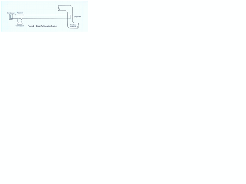

307.2.3 Auxiliary and secondary drain systems. In addition to the requirements of Section 307.2.1, where damage to any building components could occur as a result of overflow from the equipment primary condensate removal system, one of the following auxiliary protection methods shall be provided for each cooling coil or fuel-fired appliance that produces condensate:
1. An auxiliary drain pan with a separate drain shall be provided under the coils on which condensation will occur. The auxiliary pan drain shall discharge to a conspicuous point of disposal to alert occupants in the event of a stoppage of the primary drain. The pan shall have a minimum depth of 1-1/2 inches (38 mm), shall not be less than 3 inches (76 mm) larger than the unit or the coil dimensions in width and length and shall be constructed of corrosion-resistant material. Galvanized sheet steel pans shall have a minimum thickness of not less than 0.0236 inch (0.6010 mm) (No. 24 gage). Nonmetallic pans shall have a minimum thickness of not less than 0.0625 inch (1.6 mm).
2. A separate overflow drain line shall be connected to the drain pan provided with the equipment. Such overflow drain shall discharge to a conspicuous point of disposal to alert occupants in the event of a stoppage of the primary drain. The overflow drain line shall connect to the drain pan at a higher level than the primary drain connection.
3. An auxiliary drain pan without a separate drain line shall be provided under the coils on which condensate will occur. Such pan shall be equipped with a water-level detection device conforming to UL 508 that will shut off the equipment served prior to overflow of the pan. The auxiliary drain pan shall be constructed in accordance with Item 1 of this section.
4. A water-level detection device conforming to UL 508 shall be provided that will shut off the equipment served in the event that the primary drain is blocked. The device shall be installed in the primary drain line, the overflow drain line, or in the equipment-supplied drain pan, located at a point higher than the primary drain line connection and below the overflow rim of such pan.
[W] Exception s :
1. Fuel-fired appliances that automatically shut down operation in the event of a stoppage in the condensate drainage system.
2. Unducted fan coil units where there is no factory option available for water-level detection devices and are installed directly within the occupied space.
307.2.3.1 Water-level monitoring devices. On downflow units and all other coils that do not have a secondary drain or provisions to install a secondary or auxiliary drain pan, a water-level monitoring device shall be installed inside the primary drain pan. This device shall shut off the equipment served in the event that the primary drain becomes restricted. Devices installed in the drain line shall not be permitted.
Exception: Water-level monitoring devices are not required for unducted fan coil units where there is no factory option available for water-level detection devices and the units are installed directly within the occupied space.
307.2.3.2 Appliance, equipment and insulation in pans. Where appliances, equipment or insulation are subject to water damage when auxiliary drain pans fill, that portion of the appliance,equipment and insulation shall be installed above the rim of the pan. Supports located inside of the pan to support the appliance or equipment shall be water resistant and approved.
307.2.4 Traps. Condensate drains shall be trapped as required by the equipment or appliance manufacturer.
***
[B] SECTION 309
TEMPERATURE CONTROL
[B] 309.1 Space-heating systems. Interior spaces intended for human occupancy shall be provided with active or passive space-heating systems capable of maintaining an average (( a minimum on the design heating day
Exception: Interior spaces where the primary purpose is not associated with human comfort.
***
SECTION 312
HEATING AND COOLING LOAD CALCULATIONS
312.1 Load calculations. Heating and cooling system design loads for the purpose of sizing systems, appliances and equipment shall be determined in accordance with the procedures described in the (( ASHRAE/ACCA Standard 183
Alternatively, design loads shall be determined by an approved equivalent computation procedure, using the design parameters specified in Chapter 3 of the International
Energy Conservation Code.
Section 5. The following sections of Chapter 4 of the International Mechanical Code, 2012 Edition, are amended as follows:
CHAPTER 4
VENTILATION
SECTION 401
GENERAL
***
401.2 Ventilation required. Every occupied space other than enclosed parking garages, loading docks and motor vehicle repair garages shall be ventilated in accordance with Section 401.2.1 or 401.2.2. Enclosed parking garages, loading docks and motor vehicle repair garages shall be ventilated by mechanical means in accordance with Sections 403 and 404.
[W] 401.2.1 Group R occupancies. Ventilation in Group R occupancies shall be provided in accordance with the Sections 403.8 and 403.9.
401.2.2 All other occupancies. Ventilation in all other occupancies shall be provided by natural means in accordance with Section 402 or by mechanical means in accordance with Section 403. (( Where the air infiltration
rate in a dwelling unit is less than 5 air changes per hour when tested with a blower door at a pressure of 0.2-inch water column (50 Pa) in accordance with Section 402.4.1.2 of the International Energy Conservation Code, the dwelling unit shall be
ventilated by mechanical means in accordance with Section 403.
***
401.4 Intake opening location. Air intake openings shall comply with all of the following:
1. Intake openings shall be located a minimum of 10 feet (3048 mm) from lot lines or buildings on the same lot. Where openings front on a street or public way, the distance shall be measured from the opposite side of the street or public way.
2. Mechanical and gravity outdoor air intake openings shall be located not less than 10 feet (3048 mm) horizontally from any hazardous or noxious contaminant source, such as vents, streets, alleys, parking lots and loading docks, except as specified in Item 3 or Section 501.2.1. Outdoor air intake openings shall be permitted to be located less than 10 feet (3048 mm) horizontally from streets, alleys, parking lots and loading docks provided that the openings are located not less than 25 feet (7620 mm) vertically above such locations. Where openings front on a street or public way, the distance shall be measured from the closest edge of the street or public way. The exhaust from a bathroom, clothes dryer or kitchen in a dwelling shall not be considered to be a hazardous or noxious contaminant.
Exception: Enclosed parking garage and repair garage intakes are permitted to be located less than 10 feet horizontally of the street, alley, parking lots and loading docks.
3. Intake openings shall be located not less than 3 feet (914 mm) below contaminant sources where such sources are located within 10 feet (3048 mm) of the opening.
4. Intake openings on structures in flood hazard areas shall be at or above the elevation required by Section 1612 of the International Building Code for utilities and attendant equipment.
5. Intake openings shall not be located:
5.1. In a crawl space;
5.2. Less than one foot (305 mm) above a roof, adjacent grade, or other surface directly below the intake; or
5.3. Under a deck having a surface height less than three feet above grade or other surface directly below the intake.
Interpretation: For purposes of this section, lot line includes any property line separating one lot from another lot, but does not include any property line separating a lot from a public street or alley right-of-way.
***
401.7 Compliance and commissioning. Compliance with Sections 402 and 403.1 through 403.8 shall be demonstrated through engineering calculations. Documentation of calculations shall be submitted on the permit plan sets. Testing and commissioning shall be performed and documented in accordance with the International Energy Code.
SECTION 402
NATURAL VENTILATION
[B] 402.1 Natural ventilation. Natural ventilation of an occupied space shall be through windows, doors, louvers or other openings to the outdoors. The operating mechanism for such openings shall be provided with ready access so that the openings are readily controllable by the building occupants.
Exception: Automatically controlled natural ventilation systems do not require ready access and control by building occupants.
***
SECTION 403
MECHANICAL VENTILATION
***
[W] 403.2 Outdoor air required. The minimum outdoor airflow rate shall be determined in accordance with Section 403.3. (( Ventilation supply systems shall be designed to deliver the required rate of outdoor airflow to the
breathing zone within each occupiable space.
[W] Exception s :
1. Where the registered design professional demonstrates that an engineered ventilation system design will prevent the maximum concentration of contaminants from exceeding that obtainable by the rate of outdoor air ventilation determined in accordance with Section 403.3, the minimum required rate of outdoor air shall be reduced in accordance with such engineered system design.
2. Alternate systems designed in accordance with ASHRAE Standard 62.1 Section 6.2, Ventilation Rate Procedure, shall be permitted.
[W] 403.2.1 Recirculation of air. The (( outdoor
1. Ventilation air shall not be recirculated from one dwelling to another or to dissimilar occupancies.
2. Supply air to a swimming pool and associated deck areas shall not be recirculated unless such air is dehumidified to maintain the relative humidity of the area at 60 percent or less. Air from this area shall not be recirculated to other spaces where
(( more than
3. Where mechanical exhaust is required by Note b in Table 403.3, recirculation of air from such spaces shall be prohibited. All air supplied to such spaces shall be exhausted, including any air in excess of that required by Table 403.3.
4. Building HVAC air used as transfer air for heat removal may be recirculated. (( Where mechanical exhaust is required by Note g in Table 403.3, mechanical exhaust is required and recirculation is prohibited where more than 10
percent of the resulting supply airstream consists of air recirculated from these spaces.
403.2.2 Transfer air. Except where recirculation from such spaces is prohibited by Table 403.3, air transferred from occupiable spaces is not prohibited from serving as makeup air for required exhaust systems in such spaces as kitchens, baths, toilet rooms, elevators and smoking lounges. The amount of transfer air and exhaust air shall be sufficient to provide the flow rates as specified in Section 403.3. The required outdoor airflow rates specified in Table 403.3 shall be introduced directly into such spaces or into the occupied spaces from which air is transferred or a combination of both.
403.2.3 Outdoor air delivery. The outdoor air shall be ducted in a fully enclosed path directly to every air-handling unit in each zone not provided with sufficient operable opening area for natural ventilation to occur.
Exception: Ducts may terminate within 12 inches of the intake to an HVAC unit if they are physically fastened so that the outdoor air duct is directed into the unit intake.
403.3 Outdoor airflow rate. Ventilation systems shall be designed to have the capacity to supply the minimum outdoor airflow rate determined in accordance with this section. The occupant load utilized for design of the ventilation system shall not be less than the number determined from the estimated maximum occupant load rate indicated in Table 403.3. Ventilation rates for occupancies not represented in Table 403.3 shall be those for a listed occupancy classification that is most similar in terms of occupant density, activities and building construction; or shall be determined by an approved engineering analysis. The ventilation system shall be designed to supply the required rate of ventilation air continuously during the period the building is occupied, except as otherwise stated in other provisions of the code.
With the exception of smoking lounges, the ventilation rates in Table 403.3 are based on the absence of smoking in occupiable spaces. Where smoking is anticipated in a space other than a smoking lounge, the ventilation system serving the space shall be designed to provide ventilation over and above that required by Table 403.3 in accordance with accepted engineering practice.
[W] Exception: (( The occupant load is not required to be determined based on the estimated maximum occupant load rate indicated in Table 403.3 where approved statistical data document the accuracy of an alternate anticipated
occupant density.
***
[W] TABLE 403.3
MINIMUM VENTILATION RATES
| OCCUPANCY CLASSIFICATION |
OCCUPANT DENSITY |
PEOPLE OUTDOOR AIRFLOW RATE IN BREATHING ZONE, Rp CFM/PERSON |
AREA OUTDOOR AIRFLOW RATE IN BREATHING ZONE, Ra CFM/FT2 a |
EXHAUST AIRFLOW RATE CFM/FT2 a |
||||
| Correctional facilities |
||||||||
| Cells |
|
|
|
|
||||
| with plumbing fixturesg, k |
25 |
5 |
0.12 |
1.0 |
||||
| Dining halls |
||||||||
| Guard stations |
15 |
5 |
0.06 |
|||||
| Day room |
30 |
5 |
0.06 |
|||||
| Booking/waiting |
50 |
7.5 |
0.06 |
|||||
| Dry cleaners, laundries |
||||||||
| Coin-operated dry cleaner |
20 |
15 |
||||||
| Coin-operated laundries |
20 |
7.5 |
0.06 |
|||||
| Commercial dry cleaner |
30 |
30 |
||||||
| Commercial laundry |
10 |
25 |
||||||
| Storage, pick up |
30 |
7.5 |
0.12 |
|||||
| Education |
||||||||
| Auditoriums |
150 |
5 |
0.06 |
|||||
| Corridors (see public spaces) |
- |
|||||||
| Media center |
25 |
10 |
0.12 |
|||||
| Sports locker roomsg, k |
0.5 |
|||||||
| Music/theater/dance |
35 |
10 |
0.06 |
|||||
| (( |
|
|
|
|||||
| Day care (through age 4) |
25 |
10 |
0.18 |
|||||
| Classrooms (ages 5-8) |
25 |
10 |
0.12 |
|||||
| Classrooms (age 9 plus) |
35 |
10 |
0.12 |
|||||
| Lecture classroom |
65 |
7.5 |
0.06 |
|||||
| Lecture hall (fixed seats) |
150 |
7.5 |
0.06 |
|||||
| Art classroom g |
20 |
10 |
0.18 |
0.7 |
||||
| Science laboratories g, k |
25 |
10 |
0.18 |
1.0 |
||||
| Wood/metal shopsg, k |
20 |
10 |
0.18 |
0.5 |
||||
| Computer lab |
25 |
10 |
0.12 |
|||||
| Multiuse assembly |
100 |
7.5 |
0.06 |
|||||
| Locker/dressing rooms g, k |
0.25 |
|||||||
| Food and beverage service |
||||||||
| Bars, cocktail lounges |
100 |
7.5 |
0.18 |
|||||
| Cafeteria, fast food |
100 |
7.5 |
0.18 |
|||||
| Dining rooms |
70 |
7.5 |
0.18 |
|||||
| Kitchens (cooking)b |
- |
- |
- |
0.7 |
||||
| Hospitals, nursing and convalescent homes |
||||||||
| Autopsy roomsb |
0.5 |
|||||||
| Medical procedure rooms |
20 |
15 |
||||||
| Operating rooms |
20 |
30 |
||||||
| Patient rooms |
10 |
25 |
||||||
| Physical therapy |
20 |
15 |
||||||
| Recovery and ICU |
20 |
15 |
||||||
| Hotels, motels, resorts and dormitories |
||||||||
| Multipurpose assembly |
120 |
5 |
0.06 |
|||||
| Bathrooms/toilet-privateg, k |
- |
25/50f |
||||||
| Bedroom/living room |
10 |
5 |
0.06 |
|||||
| Conference/meeting |
50 |
5 |
0.06 |
|||||
| Dormitory sleeping areas |
20 |
5 |
0.06 |
|||||
| Gambling casinos |
120 |
7.5 |
0.18 |
|||||
| Lobbies/prefunction |
30 |
7.5 |
0.06 |
|||||
| Offices |
||||||||
| Conference rooms |
50 |
5 |
0.06 |
|||||
| [W] Kitchenettes |
- |
- |
- |
0.30 |
||||
| Office spaces |
5 |
5 |
0.06 |
|||||
| Reception areas |
30 |
5 |
0.06 |
|||||
| Telephone/data entry |
60 |
5 |
0.06 |
|||||
| Main entry lobbies |
10 |
5 |
0.06 |
|||||
| [W] Private dwellings, single and multiple |
||||||||
| Garages, common for |
0.75 |
|||||||
| Garages, separate for |
100 cfm per car |
|||||||
| Kitchensb |
25/100f |
|||||||
| Living areasc |
Based upon number of bedrooms. First bedroom, 2; each additional bedroom, 1 |
(( |
||||||
| Toilet rooms, (( |
20/50f |
|||||||
| Public spaces |
||||||||
| Corridors |
0.06 |
|||||||
| Elevator car Elevator lobbies in garages |
|
|
1.0 |
1.0
|
||||
| Shower room |
50/20f |
|||||||
| (( |
|
|
|
|
||||
| Toilet rooms publicg, k |
50/70e |
|||||||
| Places of religious worship |
120 |
5 |
0.06 |
|||||
| Courtrooms |
70 |
5 |
0.06 |
|||||
| Legislative chambers |
50 |
5 |
0.06 |
|||||
| Libraries |
10 |
5 |
0.12 |
|||||
| Museums (children's) |
40 |
7.5 |
0.12 |
|||||
| Museums/galleries |
40 |
7.5 |
0.06 |
|||||
| Retail stores, sales floors and showroom floors |
||||||||
| Sales (except as below) |
15 |
7.5 |
0.12 |
|||||
| Dressing rooms |
0.25 |
|||||||
| Mall common areas |
40 |
7.5 |
0.06 |
|||||
| Shipping and receiving |
- |
0.12 |
||||||
| (( |
|
|
|
|
||||
| Storage rooms |
0.12 |
|||||||
| Warehouses (see storage) |
- |
- |
||||||
| Specialty shops |
||||||||
| Automotive motor-fuel dispensing stationsb |
1.5 |
|||||||
| Barber |
25 |
(( |
0.06 |
0.5 |
||||
| Beauty salonsb |
25 |
20 |
0.12 |
0.6 |
||||
| Nail salonsb,h |
25 |
20 |
0.12 |
0.6 |
||||
| Embalming roomb |
2.0 |
|||||||
| Pet shops (animal areas)b |
10 |
7.5 |
0.18 |
0.9 |
||||
| Supermarkets |
8 |
7.5 |
0.06 |
|||||
| [W] Sports and amusement |
||||||||
| Disco/dance floors |
100 |
20 |
0.06 |
|||||
| Bowling alleys (seating areas) |
40 |
10 |
0.12 |
|||||
| Game arcades |
20 |
7.5 |
0.18 |
|||||
| Ice arenas without combustion enginesj |
0.30 |
0.5 |
||||||
| Gym, stadium, arena (play area) j |
0.30 |
|||||||
| Spectator areas |
150 |
7.5 |
0.06 |
|||||
| Swimming pools (pool and deck area) |
0.48 |
|||||||
| Health club/aerobics room |
40 |
20 |
0.06 |
|||||
| Health club/weight room |
10 |
20 |
0.06 |
|||||
| Storage |
||||||||
| [W] Janitor closets, trash rooms, recycling rooms |
- |
- |
- |
1.0 |
||||
| Repair garages d (( |
0.75 |
|||||||
| Enclosed loading docks d Enclosed parking garagesb, d Ticket booths (within enclosed parking garages)l [W] Storage rooms, chemical |
-
60 - |
-
- - |
-
- - |
1.5 0.75 - 1.5 |
||||
| Warehouses Non-retail storage spaces >100 sfk |
|
-
|
0.06 0.06 |
|
||||
| Theaters |
||||||||
| Auditoriums (see education) |
||||||||
| Lobbies |
150 |
5 |
0.06 |
|||||
| Stages, studios |
70 |
10 |
0.06 |
|||||
| Ticket booths |
60 |
5 |
0.06 |
|||||
| Transportation |
||||||||
| Platforms |
100 |
7.5 |
0.06 |
|||||
| Transportation waiting |
100 |
7.5 |
0.06 |
|||||
| Workrooms |
||||||||
| Bank vaults/safe deposit |
5 |
5 |
0.06 |
|||||
| Darkrooms |
1.0 |
|||||||
| Copy, printing rooms |
4 |
5 |
0.06 |
0.5 |
||||
| Meat processingc |
10 |
15 |
||||||
| Pharmacy (prep. area) |
10 |
5 |
0.18 |
|||||
| Photo studios |
10 |
5 |
0.12 |
|||||
| Computer (without printing) |
4 |
5 |
0.06 |
|||||
For SI: 1 cubic foot per minute = 0.0004719 m 3 /s, 1 ton = 908 kg, 1 cubic foot per minute per square foot = 0.00508 m 3 /(s * m 2 ),
degrees C = [( degrees F) -32]/1.8, 1 square foot = 0.0929 m 2 .
a. Based upon net occupiable floor area.
b. Mechanical exhaust required and the recirculation of air from such spaces is prohibited (see Section 403.2.1, Item 3).
c. Spaces unheated or maintained below 50 degrees F are not covered by these requirements unless the occupancy is continuous.
d. Ventilation systems (( in enclosed parking garages
e. Rates are per water closet or urinal. The higher rate shall be provided where the exhaust system is designed to operate intermittently. The lower rate shall be permitted only where the exhaust system is designed to operate continuously while occupied.
f. Rates are per room unless otherwise indicated. The higher rate shall be provided where the exhaust system is designed to operate intermittently. The lower rate shall be permitted only where the exhaust system is designed to operate continuously while occupied.
[W] g. Mechanical exhaust is required and recirculation is prohibited (( except that recirculation shall be permitted where the resulting supply airstream consists of not more than 10 percent air recirculated from these spaces
(see Section 403.2.1, Items 2 and 4).
h. For nail salons, each nail station shall be provided with a source capture system capable of exhausting not less than 50 cfm per station.
[W] i. A laundry area within a kitchen or bathroom is not required to have local exhaust. For the laundry area to qualify as being within the kitchen, the laundry room door must open directly into the kitchen and not into an adjacent corridor. Where there are doors that separate the laundry area from the kitchen or bathroom the door shall be louvered.
[W] j. When combustion equipment is intended to be used on the playing surface, additional dilution ventilation and/or source control shall be provided.
k. Transfer air permitted in accordance with Section 403.2.2. For non-retail storage areas, transfer air is also permitted from an adjacent open parking garage, or an enclosed parking garage or loading dock that is mechanically ventilated in accordance with Section 404.
l. This space shall be maintained at a positive pressure. See Section 404.3.
***
403.6 Variable air volume system control. Variable air volume air distribution systems, other than those designed to supply only 100-percent outdoor air, shall be provided with controls to regulate the flow of outdoor air. Such control system shall be designed to maintain the flow rate of outdoor air at a rate of not less than that required by Section 403.3 over the entire range of supply air operating rates. Calculations and a description of controls operation shall be submitted with the permit drawings.
***
[W] 403.8 Ventilation systems for Group R occupancies. Each dwelling unit or sleeping unit shall be equipped with local exhaust and whole house ventilation systems and shall comply with Sections 403.8.1 through 403.8.10. All occupancies other than Group R occupied spaces that support the Group R occupancy shall meet the ventilation requirements of Section 402 or Sections 403.1 to 403.7.
403.8.1 Minimum ventilation performance. Ventilation systems shall be designed and installed to satisfy the ventilation requirements of Table 403.3 or Table 403.8.1. Breathing zone ventilation rates from Table 403.3 shall be calculated per Section 403.3.1.1 and corrected per zone air distribution effectiveness requirements per Section 403.3.1.2.
Table 403.8.1
Ventilation Rates for All Group R Private Dwellings, Single and Multiple
(Continuously Operating Systems)
| Floor Area (ft2) |
Bedrooms1 |
||||
| 0-1 |
2-3 |
4-5 |
6-7 |
>7 |
|
| <1500 |
30 |
45 |
60 |
75 |
90 |
| 1501 3000 |
45 |
60 |
75 |
90 |
105 |
| 3001 4500 |
60 |
75 |
90 |
105 |
120 |
| 4501 6000 |
75 |
90 |
105 |
120 |
135 |
| 6001 7500 |
90 |
105 |
120 |
135 |
150 |
| >7500 |
105 |
120 |
135 |
150 |
165 |
1 Ventilation rates in table are minimum outdoor airflow rates measured in cfm.
403.8.2 Control and operation . Controls for and operation of ventilation systems shall comply with this section.
Exception: Engineered central ventilation systems serving dwelling units or sleeping units are not required to have individual controls for each dwelling unit or sleeping unit when designed for continuous operation and approved by the code official.
1. Location of controls. Controls for all ventilation systems shall be readily accessible by the occupant.
2. Instructions. Operating instructions for whole house ventilation systems shall be provided to the occupant by the installer of the system.
3. Local exhaust ventilation systems. Local exhaust ventilation systems shall be controlled by manual switches, dehumidistats, timers, or other approved means.
4. Continuous whole house ventilation systems. Continuous whole house ventilation systems shall operate continuously. Exhaust fans, forced-air system fans, or supply fans shall be equipped with "fan on" as override controls. Controls shall be capable of operating the ventilation system without energizing other energy-consuming appliances. A label shall be affixed to the controls that reads "Whole House Ventilation (see operating instructions)."
5. Intermittent whole house ventilation systems. Intermittent whole house ventilation systems shall comply with the following:
5.1 They shall be capable of operating intermittently and continuously.
5.2 They shall have controls capable of operating the exhaust fans, forced-air system fans, or supply fans without energizing other energy-consuming appliances.
5.3 The ventilation rate shall be adjusted according to the exception in Section 403.8.5.1.
5.4 The system shall be designed so that it can operate automatically based on the type of control timer installed.
5.5 The intermittent mechanical ventilation system shall operate at least one hour out of every four.
5.6 The system shall have a manual control and automatic control, such as a 24-hour clock timer.
5.7 At the time of final inspection, the automatic control shall be set to operate the whole house fan according to the schedule used to calculate the whole house fan sizing.
5.8 A label shall be affixed to the control that reads "Whole House Ventilation (see operating instructions)."
403.8.3 Outdoor air intake locations. Outdoor air intakes shall be classified as either operable openings or mechanical air intakes. The intake locations for operable openings and mechanical air intakes shall comply with the following:
1. Openings for mechanical air intakes shall comply with Section 401.4. Operable openings shall comply with Section 401.4 items 2, 4 and 5 only.
2. Intake openings shall not be located closer than 10 feet from an appliance vent outlet unless such vent outlet is 3 feet above the outdoor air inlet. The vent shall be permitted to be closer if specifically allowed by Chapter 8 or by the International Fuel Gas Code.
3. Intake openings shall be located where they will not pick up objectionable odors, fumes, or flammable vapors.
4. Intake openings shall be located where they will not take air from a hazardous or unsanitary location.
5. Intake openings shall be located where they will not take air from a room or space having a fuel-burning appliance.
6. Intake openings shall not be located closer than 10 feet from a vent opening of a plumbing drainage system unless the vent opening is at least 3 feet above the air inlet.
7. Intake openings shall not be located where they will take air from an attic, crawl space, or garage.
403.8.4 Local exhaust ventilation requirements. Local exhaust ventilation systems shall exhaust at least the volume of air required for exhaust in Table 403.3. Exhaust shall be provided in each kitchen, bathroom, water closet, laundry area, indoor swimming pool, spa, and other rooms where water vapor or cooking odor is produced. Local exhaust ventilation ducts shall terminate outdoors.
403.8.4.1 Local exhaust systems. Exhaust systems shall be designed and installed to meet all of the criteria below:
1. Local exhaust shall be discharged outdoors.
2. Exhaust outlets shall comply with Section 501.3.
3. Pressure equalization shall comply with Section 501.4.
4. Exhaust ducts in systems which are designed to operate intermittently shall be equipped with backdraft dampers.
5. All exhaust ducts in unconditioned spaces shall be insulated to a minimum of R-4.
6. Terminal outlet elements shall have at least the equivalent net free area of the ductwork.
7. Terminal outlet elements shall be screened or otherwise protected as required by Section 501.3.2.
8. Exhaust fans in separate dwelling units or sleeping units shall not share common exhaust ducts unless the system is engineered for this operation.
9. Where permitted by Chapter 5, multiple local exhaust ducts may be combined. If more than one of the exhaust fans in a dwelling unit or sleeping unit shares a common exhaust duct then each exhaust fan shall be equipped with a backdraft damper to prevent the recirculation of exhaust air from one room to another room via the exhaust ducting system.
403.8.4.2 Local exhaust fans. Exhaust fan construction and sizing shall meet the following criteria.
1. Exhaust fans shall be tested and rated in accordance with the airflow and sound rating procedures of the Home Ventilating Institute: HVI 915 Loudness Testing and Rating Procedure; HVI 916 Airflow Test Procedure; and HVI 920 Product Performance Certification Procedure
Exception : Range hoods and down-draft exhaust fans used for local exhaust for kitchens are not required to be rated.
2. Fan airflow rating and duct systems shall be designed and installed to deliver at least the exhaust airflow required by Table 403.3. The airflows required refer to the delivered airflow of the system as installed and tested using a flow hood, flow grid, or other airflow measurement device.
EXCEPTIONS :
1. An exhaust airflow rating at a pressure of 0.25 in. w.g. may be used, provided the duct sizing meets the prescriptive requirements of Table 403.8.4.2.
2. Where a range hood or down-draft exhaust fan is used to satisfy the local exhaust requirements for kitchens, the range hood or down draft exhaust shall not be less than 100 cfm at 0.10 in. w.g.
Table 403.8.4.2
Prescriptive Exhaust Duct Sizing
| Fan Tested cfm at 0.25 inches w.g. |
Minimum Flex Diameter |
Maximum Length in Feet |
Minimum Smooth Diameter |
Maximum Length in Feet |
Maximum Elbows1 |
| 50 |
4 inches |
25 |
4 inches |
70 |
3 |
| 50 |
5 inches |
90 |
5 inches |
100 |
3 |
| 50 |
6 inches |
No Limit |
6 inches |
No Limit |
3 |
| 80 |
4 inches2 |
NA |
4 inches |
20 |
3 |
| 80 |
5 inches |
15 |
5 inches |
100 |
3 |
| 80 |
6 inches |
90 |
6 inches |
No Limit |
3 |
| 100 |
5 inches2 |
NA |
5 inches |
50 |
3 |
| 100 |
6 inches |
45 |
6 inches |
No Limit |
3 |
| 125 |
6 inches |
15 |
6 inches |
No Limit |
3 |
| 125 |
7 inches |
70 |
7 inches |
No Limit |
3 |
1. For each additional elbow, subtract 10 feet from length.
2. Flex ducts of this diameter are not permitted with fans of this size.
403.8.5 Whole house ventilation requirements. All whole house ventilation systems shall comply with Sections 403.8.5.1 and 403.8.5.2. Each dwelling unit or sleeping unit shall be equipped with one of the following four types of mechanical whole house ventilation systems:
1. A system using exhaust fans (see Section 403.8.6);
2. A system integrated with forced-air systems (see Section 403.8.7);
3. A system using supply fans (see Section 403.8.8); or
4. A heat or energy recovery ventilation system (see Section 403.8.9).
The whole house exhaust system is permitted to be one of the local exhaust systems required by Section 403.8.4 as long as the requirements of this section, in addition to the requirements of Section 403.8.4, are met.
403.8.5.1 Outdoor air. Outdoor air shall be distributed to each habitable space. Where outdoor air supply intakes are separated from exhaust vents by doors, means shall be provided to ensure airflow to all separated habitable spaces by installing distribution ducts, installed grilles, transoms, doors undercut to a minimum of 1/2inch above the surface of the finish floor covering, or other similar means where permitted by the International Building Code.
The mechanical system shall operate continuously to supply at least the volume of outdoor air required in Table 403.3 or Table 403.8.1.
EXCEPTION : Intermittently operating ventilation systems: The whole house mechanical ventilation system is permitted to operate intermittently where the system has controls that enable operation for not less than 25 percent of each 4-hour segment and the ventilation rate prescribed in Table 403.3 or Table 403.8.1 is multiplied by the factor determined in accordance with Table 403.8.5.1.
The intermittent mechanical ventilation system shall operate at least one hour out of every four. A minimum of two
Table 403.8.5.1
Intermittent Whole House Mechanical Ventilation Rate Factors a, b
| Run-Time Percentage in Each 4-Hour Segment |
25% |
33% |
50% |
66% |
75% |
100% |
| Ventilation Rate Factor (Fv)a |
4 |
3 |
2 |
1.5 |
1.3 |
1.0 |
a For ventilation system run-time values between those given, the factors are permitted to be determined by interpolation.
b Extrapolation beyond the table is prohibited.
Intermittent Mechanical Ventilation Airflow Calculation Examples:
Example #1: Calculating fan airflow based on Table 403.8.5.1 values:
An intermittently operated whole house fan that serves a dwelling unit with a continuous ventilation requirement of 30 CFM (from Table 403.3 or 403.8.1) is controlled to operate with an on-time of 3 hours and off-time of 1 hours throughout the day.
The minimum intermittent ventilation rate is calculated as follows:
Q r = 30 CFM (from Table 403.3 or 403.8.1)
Cycle time = 4 hours
(where: cycle time is equal to the on-time plus the offtime)
Run-time percentage = 3 / 4 = 75%
(where: f is equal to the on-time divided by the cycle time)
Ventilation rate factor (F v ) 1.3 (from Table 403.8.5.1)
Q f = Q r x F v = 30 CFM x 1.3 = 39
Example #2: Calculating fan airflow based on footnote a to Table 403.8.5.1:
An intermittently operated whole house fan that serves a dwelling unit with a continuous ventilation requirement of 30 CFM (from Table 403.3 or 403.8.1) is controlled to operate with an on-time of 1 hours and off-time of 3 hour throughout the day.
The minimum intermittent ventilation rate is calculated as follows:
Qr = 30 CFM (from Table 403.3 or 403.8.1)
Cycle time = 4 hours
(where: cycle time is equal to the on-time plus the offtime)
Run-time percentage = 1/4 = 25% (this is greater than 50%)
(where: f is equal to the on-time divided by the cycle time)
Ventilation rate factor F v = 4 (per footnote a of Table 403.8.5.1)
Q f = Q r x F v = 30 CFM x 4 = 120 CFM
See ASHRAE 62.2 Appendix B for further explanation and examples.
403.8.5.2 Whole house supply system general requirements. Whole house ventilation systems integrated with a forced-air system, systems using supply fans and systems using a heat or energy recovery ventilation system shall comply with the following.
1. Outdoor air louvers shall be adequately sized for the required airflow and shall comply with Section 401.5. Outdoor air intake locations shall comply with mechanical air intake requirements of Section 403.8.3.
2. Outdoor air ducts for ventilation integrated with forced air systems and exhaust ducts for heat or energy recovery systems shall be provided with a means for balancing the system to the required airflow via balance dampers or other devices.
3. Outdoor air ducts, for ventilation integrated with forced air systems shall be provided with motorized dampers.
E xceptions :
1. Outdoor air ducts at heat or energy recovery ventilation systems are not required to have motorized dampers.
2. Outdoor air ducts at continuous ventilation systems are not required to have motorized dampers.
4. Outdoor air ducts in the conditioned space shall be insulated to a minimum of R-4. In heat or energy recovery ventilation systems, ducts upstream of the heat exchanger shall also be insulated to at least R-4.
Note: See Seattle Energy Code for additional insulation requirements.
5. All outdoor air ducts shall be designed and installed to deliver at least the outdoor airflow required by Section 403.8.5.1. The airflows required refer to the delivered airflow of the system as installed and tested using a flow hood, flow grid, or other airflow measurement device.
E xception : The outdoor air duct for supply fan systems and heat or energy recovery systems may be prescriptively sized per Table 403.8.5.2 for dedicated outdoor air ducts upstream of the supply fan. Supply fans shall have the capacity to provide the amount of outdoor air required by Section 403.8.5.1 at 0.40 in. w.g. in accordance with HVI 916, Home Ventilation Institute Airflow Test Procedure. When prescriptively sized the system shall be tested and balanced using a flow hood, flow-grid, or other airflow measurement device.
6. Whole house ventilation controls for intermittent operation shall allow concurrent operation of the forced-air fan and the associated outdoor air motorized damper.
7. Whole house ventilation controls for continuous operation shall be provided at the forced-air fan.
Table 403.8.5.2
Prescriptive Supply Fan Duct Sizing
| Supply Fan Tested cfm at 0.40 " w.g. |
||
| Specified Volume from Table 408.1 |
Minimum Smooth Duct Diameter |
Minimum Flexible Duct Diameter |
| 50 90 cfm |
4 inch |
5 inch |
| 90 150 cfm |
5 inch |
6 inch |
| 150 250 cfm |
6 inch |
7 inch |
| 250 400 cfm |
7 inch |
8 inch |
403.8.6 Whole house ventilation with exhaust fan systems. This section establishes minimum requirements for mechanical whole house ventilation systems using exhaust fans.
403.8.6.1 Outdoor air. Exhaust fan only ventilation systems shall provide outdoor air to each occupiable space through one of the following methods:
1. Outdoor air may be drawn through air inlets installed in exterior walls or windows. The air inlets shall comply with all of the following:
1.1. Inlets shall have controllable, secure openings and shall be designed to not compromise the thermal properties of the building envelope.
1.2. Inlets shall be readily accessible to occupants , including compliance with Section 1109.13 of the International Building Code for designated Accessible units, Type A units and Type B units .
1.3. Inlets shall be screened or otherwise protected from entry by insects, leaves, or other material.
1.4. Inlets shall provide not less than 4 square inches of net free area of opening for each 10 cfm of outdoor air required in Table 403.3 or Table 403.8.1.
1.5. Any inlet or combination of inlets which provide 10 cfm at 10 pascals as in accordance with HVI 916 Home Ventilation Institute Air Flow Test Procedure, and HVI 920 Home Ventilation Institute Product Performance Certification Procedure are deemed equivalent to 4 square inches of net free area.
1.6. Each occupiable space shall have a minimum of one air inlet that has a minimum of 4 square inches of net free area.
2. In high-rise buildings, outdoor air may be drawn in through operable windows, doors, louvers or other operable openings to the outdoors. Exterior spaces shall have a minimum openable area of 4 percent of the total floor area being ventilated. Doors exiting to a corridor, court or public way shall not be used to provide outdoor air. The operable openings shall comply with the following:
2.1. Openings shall be controllable, securable, and shall be designed to not compromise the thermal properties of the building envelope.
2.2. Openings shall be readily accessible to occupants , including compliance with Section 1109.13 of the International Building Code for designated Accessible units, Type A units and Type B units .
3. For interior adjoining spaces without outdoor air openings, one of the following two options shall be used to ventilate the interior adjoining space:
3.1. Provide a whole house transfer fan at the interior adjoining space sized to provide a minimum of the ventilation rate required per Section 403.8.5.1. The transfer fan shall circulate air between the interior room or space and the adjacent habitable space. The transfer fan may operate continuously or intermittently using controls per Section 403.8.2.
3.2. Provide a permanent opening to the interior adjoining space. Opening shall be unobstructed and shall have an area of not less than 8 percent of the floor area of the interior adjoining space, but not less than 25 square feet.
403.8.6.2 Outside air intake locations. All outside air intake opening types described in Section 403.8.6.1 shall be classified as operable openings and shall not be classified as mechanical air intakes. The intake locations shall comply with Section 403.8.3.
403.8.6.3 Whole house exhaust system. Whole house exhaust system shall be designed and installed to meet all of the applicable criteria below:
1. Whole house ventilation exhaust shall be discharged outdoors.
2. Exhaust outlets shall comply with Section 501.3.2.
3. Exhaust ducts in systems which are designed to operate intermittently shall be equipped with backdraft dampers.
4. All exhaust ducts in unconditioned spaces shall be insulated to a minimum of R-4.5. Terminal outlet elements shall have at least the equivalent net free area of the ductwork.
5. Terminal outlet elements shall be screened or otherwise protected as required by Section 501.3.2.
6. One of the required local exhaust fans for the laundry room or bathroom may be designated as the whole house exhaust fan.
7. Exhaust fans in separate dwelling units or sleeping units shall not share common exhaust ducts unless the system is engineered for this operation.
8. Where permitted by Chapter 5, whole house exhaust ducts may be combined with other local exhaust ducts. If more than one of the exhaust fans in a dwelling unit or sleeping unit shares a common exhaust duct then each exhaust fan shall be equipped with a backdraft damper to prevent the recirculation of exhaust air from one room to another room via the exhaust ducting system.
403.8.6.4 Whole house exhaust and transfer fans. Exhaust fan construction and sizing shall meet the following criteria.
1. Exhaust and transfer fans shall be tested and rated in accordance with the airflow and sound rating procedures of the HVI 915 Loudness Testing and Rating Procedure; HVI 916 Airflow Test Procedure, and HVI 920 Product Performance Certification Procedure.
2. Installation of system or equipment shall be carried out in accordance with manufacturers' design requirements and installation instructions.
3. Fan airflow rating and duct system shall be designed and installed to deliver at least the outdoor airflow required by Table 403.3 or Table 403.8.1. The airflows required refer to the delivered airflow of the system as installed and tested using a flow hood, flow grid, or other airflow measurement device.
E xception : An airflow rating at a pressure of 0.25 in. w.g. may be used, provided the duct sizing meets the prescriptive requirements of Table 403.8.5.2.
403.8.6.5 Fan noise. Whole house exhaust and transfer fans located 4 feet or less from the interior grille shall have a sone rating of 1.0 or less measured at 0.10 inches water gauge. Manufacturer's noise ratings shall be determined in accordance with HVI 915 Loudness Testing and Rating Procedure. Remotely mounted fans shall be acoustically isolated from the structural elements of the building and from attached ductwork using insulated flexible duct or other approved material.
403.8.7 Whole house ventilation integrated with forced-air systems. This section establishes minimum requirements for mechanical whole house ventilation systems using forced-air system fans.
403.8.7.1 Outdoor air. Forced-air system fan ventilation systems shall provide outdoor air through one of the following methods:
1. A dedicated outdoor air louver and outdoor air duct for each dwelling unit or sleeping unit shall supply outdoor air to the return side of the forced-air system fan; or
2. A central outdoor air delivery system that supplies multiple dwelling units or sleeping units shall supply outdoor air to the return side of the forced air system fan.
403.8.7.2 Whole house forced-air system. Where outdoor air is provided to each habitable dwelling unit or sleeping unit by a forced air system, the outdoor air duct shall be connected to the return air stream at a point within 4 feet upstream of the forced-air unit. It shall not be connected directly to the forced-air unit cabinet in order to prevent thermal shock to the heat exchanger. At a minimum, filtration of the outdoor air shall be provided at the forced-air unit. The filter shall be accessible for regular maintenance and replacement. The filter shall have a Minimum Efficiency Rating Value (MERV) of at least 6.
403.8.8 Whole house ventilation with supply fan systems. This section establishes minimum requirements for mechanical whole house ventilation systems using supply fan systems.
403.8.8.1 Outdoor air. Supply fan ventilation systems shall provide outdoor air through one of the following methods:
1. A dedicated outdoor air louver and outdoor air duct for each dwelling unit or sleeping unit shall supply outdoor air to a supply fan; or
2. A central outdoor air supply fan system shall distribute unconditioned or conditioned air to multiple dwelling units or sleeping units.
403.8.8.2 Whole house supply system. Where outdoor air is provided to each habitable dwelling unit or sleeping unit by supply fan systems the outdoor air shall be filtered.
The system filter may be located at the intake device or in line with the fan. The filter shall be accessible for regular maintenance and replacement. The filter shall have a Minimum Efficiency Rating Value (MERV) of at least 6.
403.8.9 Whole house ventilation with heat recovery or energy recovery ventilation systems. This section establishes minimum requirements for mechanical whole house ventilation systems using heat recovery or energy recovery ventilation systems.
403.8.9.1 Outdoor air. Heat recovery or energy recovery ventilation systems shall provide outdoor air through one of the following methods:
1. A dedicated outdoor air louver and outdoor air duct for each dwelling unit or sleeping unit shall supply outdoor air to the heat recovery or energy recovery ventilator; or
2. A central outdoor air heat recovery or energy recovery unit shall distribute conditioned air to multiple dwelling units or sleeping units.
403.8.9.2 Whole house heat recovery ventilator system. Where outdoor air is provided to each habitable dwelling unit or sleeping unit by heat recovery or energy recovery ventilator the outdoor air shall be filtered. The filter shall be located on the upstream side of the heat exchanger in both the intake and exhaust airstreams with a Minimum Efficiency Rating Value (MERV) of at least 6. The system filter may be located at the intake device or in line with the fan. The filter shall be accessible for regular maintenance and replacement.
403.8.10 Local exhaust ventilation and whole house ventilation alternate performance or design requirements. In lieu of complying with Sections 403.8.4 or 403.8.5 compliance with the section shall be demonstrated through engineering calculations by an engineer licensed to practice in the state of Washington or by performance testing. Documentation of calculations or performance test results shall be submitted to and approved by the code official. Performance testing shall be conducted in accordance with approved test methods.
403.8.11 Alternate systems. When approved by the code official, systems designed in accordance with ASHRAE Standard 62.2 shall be permitted.
403.9 Corridors. Air movement in corridors shall comply with Section 601 of this code and the International Building Code.
SECTION 404
VENTILATION OF ENCLOSED MOTOR VEHICLE OCCUPANCIES
(( ENCLOSED PARKING GARAGES
404.1 Enclosed parking garage(( s be permitted to
1. The system shall be arranged to operate automatically upon detection of vehicle operation or the presence of occupants by approved automatic detection devices.
2. The system shall be arranged to operate automatically by means of carbon monoxide detectors applied in conjunction with nitrogen dioxide detectors that modulate the ventilation system by staging fans or varying fan speed to maintain gas concentrations below specified maximum levels . Such detectors shall be designed for the specific use and installed in accordance with their manufacturers' recommendations. Mechanical ventilation systems and gas sensor systems controls shall comply with Section 1412.9 of the International Energy Conservation Code.
404.1.1 Ventilation makeup air. Ventilation makeup air shall be mechanically supplied to levels of enclosed loading docks and parking garages more than 3 stories above or below the nearest garage or loading dock entrance or exit.
404.1.2 Exhaust termination point. Exhaust termination points shall comply with Section 501.3.1.1.
404.2 Minimum ventilation.
404.2.1 Enclosed parking garages and motor vehicle repair garages. In enclosed parking garages and motor vehicle repair garages, (( A
Exception: Ventilation systems located in areas with automated parking systems where the engines of the motor vehicles are not operating shall provide a continuous ventilation airflow rate of 50 cfm per parking stall. This exception does not apply to the vehicle drop off area.
404.2.2 Enclosed loading docks. In enclosed loading docks automatic operation of the system shall not reduce the ventilation airflow rate below 1.0 cfm per square foot (0.00507 m 3 /s ??? m 2 ) of the floor area and the ventilation systems shall be capable of producing a ventilation airflow rate of 1.5 cfm per square foot (0.0076 m 3 /s * m 2 ) of floor area.
404.3 Occupied spaces accessory to public garages and motor vehicle repair garages . Connecting offices, waiting rooms, ticket booths , elevator lobbies and similar uses that are accessory to a public garage or motor vehicle repair garage shall be maintained at a positive pressure relative to the garage and shall be provided with ventilation in accordance with Section 403.3.
404.4 Motor vehicle repair garages. In buildings used for the repair of motor vehicles, each repair stall or stand shall be equipped with an exhaust capture system that connects directly to the repair engine exhaust source and prevents the escape of fumes. The exhaust system shall exhaust to the outdoor atmosphere. See Section 502.15 for additional requirements. Ventilation shall be provided for the motor vehicle repair garage in accordance with Section 404.
SECTION 405
SYSTEMS CONTROL
405.1 General. Mechanical ventilation systems shall be provided with manual or automatic controls that will operate such systems whenever the spaces are occupied. Airconditioning systems that supply required ventilation air shall be provided with controls designed to automatically maintain the required outdoor air supply rate during occupancy. Additional mechanical system control requirements are contained in the International Energy Code.
SECTION 406
VENTILATION OF UNINHABITED SPACES
406.1 General. (( Uninhabited spaces, such as crawl ,
Section 6. The following sections of Chapter 5 of the International Mechanical Code, 2012 Edition, are amended as follows:
CHAPTER 5
EXHAUST SYSTEMS
SECTION 501
GENERAL
***
501.3 Exhaust discharge. The air removed by every mechanical exhaust system shall be discharged outdoors at a point where it will not cause a nuisance and not less than the distances specified in Section 501.3.1. The air shall be discharged to a location from which it cannot again be readily drawn in by a ventilating system. Air shall not be exhausted into an attic or crawl space.
Exceptions:
1. Whole-house ventilation-type attic fans shall be permitted to discharge into the attic space of dwelling units having private attics.
2. Commercial cooking recirculating systems are not required to discharge outdoors if the kitchen area has an exhaust system that is vented to the outside. Ventilation shall be provided in accordance with Chapter 4.
501.3.1 Location of exhaust outlets. The termination point of exhaust outlets and ducts discharging to the outdoors shall be located with the following minimum distances:
1. For ducts conveying explosive or flammable vapors, fumes or dusts: 30 feet (9144 mm) from property lines; 10 feet (3048 mm) from operable openings into buildings; 6 feet (1829 mm) from exterior walls and roofs; 30 feet (9144 mm) from combustible walls and operable openings into buildings which are in the direction of the exhaust discharge; 10 feet (3048 mm) above adjoining grade.
Interpretation: Item 1 includes carpentry shop exhaust, industrial chemical lab, paint shop and sandblasting exhaust systems.
2. For other product-conveying outlets: 10 feet (3048 mm) from the property lines; 3 feet (914 mm) from exterior walls and roofs; 10 feet (3048 mm) from operable openings into buildings; 10 feet (3048 mm) above adjoining grade.
Interpretation: Item 2 includes central vacuum systems, dry cleaner, photo lab, school chemical lab, nail salon source capture system exhaust and combustion engine exhaust.
[W] 3. For all environmental air exhaust other than enclosed parking garage and transformer vault exhaust : 3 feet (914 mm) from property lines; 3 feet (914 mm) from operable openings into buildings for all occupancies other than Group U, and 10 feet (3048 mm) from mechanical air intakes. Such exhaust shall not be considered hazardous or noxious.
Exceptions:
1. The separation between an air intake and exhaust outlet on a single listed package HVAC unit.
2. Exhaust from environmental air systems other than garages may be discharged into an open parking garage.
3. Except for Group I occupancies, where ventilation system design circumstances require building HVAC air to be relieved, such as during economizer operation, such air may be relieved into an open or enclosed parking garage within the same building.
4. Exhaust outlets serving structures in flood hazard areas shall be installed at or above the elevation required by Section 1612 of the International Building Code for utilities and attendant equipment.
5. For enclosed parking garage, loading dock, and motor vehicle repair garage exhaust outlets: Exhaust ventilation openings and duct terminations shall be located not less than 10 feet (3048 mm) from property lines, operable openings into buildings, and mechanical air intakes; 10 feet (3048 mm) above adjoining finished walking surfaces other than alleys. Exhaust outlets extending to the roof shall extend 3 feet (914 mm) above the roof surface.
[W] 6. For elevator machinery rooms in enclosed or open parking garages: Exhaust outlets may discharge air directly into the parking garage.
7. For transformer vault exhaust systems: Exhaust ventilation openings and duct terminations shall be located not less than 10 feet (3048 mm) from fire escapes, required means of egress at the exterior of the building, elements of the exit discharge, combustible exterior wall coverings, unprotected openings, operable openings and property lines other than a public way. Exhaust outlets shall be located on the exterior of the building. See Seattle Building Code Section 426 for additional requirements.
(( 5
(( 5.1
(( 5.2
(( 5.3
(( 5.4
(( 5.5
(( 5.6
(( 5.7
501.3.1.1 Exhaust discharge. Exhaust air shall not be directed onto walkways in such a manner that the users of the walkway are subjected to the exhaust air stream .
Note: Seattle Land Use Code (Municipal Code Title 23) requires that the venting of odors, vapors, smoke, cinders, dust, gas and fumes shall be at least 10 feet (3048 mm) above finished sidewalk grade, and directed away as much as possible from residential uses within 50 feet (15 240 mm) of the vent in some locations.
501.3.2 Exhaust opening protection. Exhaust openings that terminate outdoors shall be protected with corrosion-resistant screens, louvers or grilles. Openings in screens, louvers and grilles shall be sized not less than 1/4 inch (6 mm) and not larger than 1/2 inch (13 mm). Openings shall be protected against local weather conditions. Louvers that protect exhaust openings in structures located in hurricane-prone regions, as defined in the International Building Code, shall comply with AMCA Standard 550. Outdoor openings located in exterior walls shall meet the provisions for exterior wall opening protectives in accordance with the International Building Code.
[W] 501.4 Pressure equalization. Mechanical exhaust systems shall be sized to remove the quantity of air required by this chapter to be exhausted. The system shall operate when air is required to be exhausted. Where mechanical exhaust is
required in a room or space (( in other than occupancies in R-3 and dwelling units in R-2
Exception: R-3 occupancies and dwelling units in R-2 occupancies are excluded from the pressure equalization requirement unless required by Section 504.5 or Section 505.2.
***
SECTION 502
REQUIRED SYSTEMS
502.1 General. An exhaust system shall be provided, maintained and operated as specifically required by this section and for all occupied areas where machines, vats, tanks, furnaces, forges, salamanders and other appliances, equipment and processes in such areas produce or throw off dust or particles sufficiently light to float in the air, or which emit heat, odors, fumes, spray, gas or smoke, in such quantities so as to be irritating or injurious to health or safety. These exhaust systems are considered product-conveying systems.
502.1.1 Exhaust inlet location. The inlet to an exhaust system shall be located in the area of heaviest concentration of contaminants.
[F] 502.1.2 Fuel-dispensing areas. The bottom of an air inlet or exhaust opening in fuel-dispensing areas shall be located not more than 18 inches (457 mm) above the floor.
502.1.3 Equipment, appliance and service rooms. Equipment , appliance and system service rooms that house sources of odors, fumes, noxious gases, smoke, steam, dust, spray or other contaminants shall be designed and constructed so as to prevent spreading of such contaminants to other occupied parts of the building.
[F] 502.1.4 Hazardous exhaust. The mechanical exhaust of high concentrations of dust or hazardous vapors shall conform to the requirements of Section 510.
***
[F] 502.4 Stationary storage battery systems. Stationary storage battery systems having a liquid capacity of more than 50 gallons , as regulated by Section 608 of the International Fire Code, shall be provided with ventilation in accordance with
this chapter and Section s 502.4.1 (( or
Exception: Lithium-ion batteries shall not require ventilation.
[F] 502.4.1 Hydrogen limit in rooms. For flooded lead acid, flooded nickel cadmium and VRLA batteries, the ventilation system shall be designed to limit the maximum concentration of hydrogen to 1.0 percent of the total volume of the room.
[F] 502.4.2 Ventilation rate in rooms. Continuous ventilation shall be provided at a rate of not less than 1 cubic foot per minute per square foot (cfm/ft 2 ) [0.00508 m3/(s * ?m 2 )] of floor area of the room.
502.4.3 Supervision. Mechanical ventilation systems required by Section 502.4 shall be supervised by an approved central, proprietary or remote station service or shall initiate an audible and visual signal at a constantly attended on-site location.
***
[F] 502.7 Application of flammable finishes. Mechanical exhaust as required by this section shall be provided for operations involving the application of flammable finishes. Spray finishing operations conducted in Group A, E, I or R occupancies shall be located in a spray room protected with an approved automatic sprinkler system installed in accordance with International Building Code Section 903.3.1.1 and separated vertically and horizontally from other areas in accordance with the International Building Code. In other occupancies, spray-finishing operations shall be conducted in a spray room, spray booth or limited spraying area approved for such use.
[F] 502.7.1 During construction. Ventilation shall be provided for operations involving the application of materials containing flammable solvents in the course of construction, alteration or demolition of a structure.
[F] 502.7.2 Limited spraying spaces. Positive mechanical ventilation which provides a minimum of six complete air changes per hour shall be installed in limited spraying spaces. Such system shall meet the requirements of the International Fire Code for handling flammable vapors. Explosion venting is not required.
Exception: Negative mechanical ventilation, providing a minimum of six complete air changes per hour, is allowed in lieu of positive mechanical ventilation if a fan rated for Class I, Division 2 hazardous locations in accordance with the Seattle Electrical Code is installed.
[F] 502.7.3 Flammable vapor areas. Mechanical ventilation of flammable vapor areas shall be provided in accordance with Sections 502.7.3.1 through 502.7.3.6.
[F] 502.7.3.1 Operation. Mechanical ventilation shall be kept in operation at all times while spraying operations are being conducted and for a sufficient time thereafter to allow vapors from drying coated articles and finishing material residue to be exhausted. Spraying equipment shall be interlocked with the ventilation of the flammable vapor area such that spraying operations cannot be conducted unless the ventilation system is in operation.
[F] 502.7.3.2 Recirculation. Air exhausted from spraying operations shall not be recirculated.
Exceptions:
1. Air exhausted from spraying operations shall be permitted to be recirculated as makeup air for unmanned spray operations provided that:
1.1. The solid particulate has been removed.
1.2. The vapor concentration is less than 25 percent of the lower flammable limit (LFL).
1.3. Approved equipment is used to monitor the vapor concentration.
1.4. An alarm is sounded and spray operations are automatically shut down if the vapor concentration exceeds 25 percent of the LFL.
1.5. In the event of shutdown of the vapor concentration monitor, 100 percent of the air volume specified in Section 510 is automatically exhausted.
2. Air exhausted from spraying operations is allowed to be recirculated as makeup air to manned spraying operations where all of the conditions provided in Exception 1 are included in the installation and documents have been prepared to show that the installation does not pose a life safety hazard to personnel inside the spray booth, spraying space or spray room.
[F] 502.7.3.3 Air velocity. Ventilation systems shall be designed, installed and maintained such that the average air velocity over the open face of the booth, or booth cross section in the direction of airflow during spraying operations, is not less than 100 feet per minute (0.51 m/s).
[F] 502.7.3.4 Ventilation obstruction. Articles being sprayed shall be positioned in a manner that does not obstruct collection of overspray.
[F] 502.7.3.5 Independent ducts. Each spray booth and spray room shall have an independent exhaust duct system discharging to the outdoors.
Exceptions:
1. Multiple spray booths having a combined frontal area of 18 square feet (1.67 m 2 ) or less are allowed to have a common exhaust where identical spray-finishing material is used in each booth. If more than one fan serves one booth, such fans shall be interconnected so that all fans operate simultaneously.
2. Where treatment of exhaust is necessary for air pollution control or energy conservation, ducts shall be allowed to be manifolded if all of the following conditions are met:
2.1. The sprayed materials used are compatible and will not react or cause ignition of the residue in the ducts.
2.2. Nitrocellulose-based finishing material shall not be used.
2.3. A filtering system shall be provided to reduce the amount of overspray carried into the duct manifold.
2.4. Automatic sprinkler protection shall be provided at the junction of each booth exhaust with the manifold, in addition to the protection required by this chapter.
[F] 502.7.3.6 Fan motors and belts. Electric motors driving exhaust fans shall not be placed inside booths or ducts. Fan rotating elements shall be nonferrous or nonsparking or the casing shall consist of, or be lined with, such material. Belts shall not enter the duct or booth unless the belt and pulley within the duct are tightly enclosed.
[F] 502.7.4 Dipping operations. Flammable vapor areas of dip tank operations shall be provided with mechanical ventilation adequate to prevent the dangerous accumulation of vapors. Required ventilation systems shall be so arranged that the failure of any ventilating fan will automatically stop the dipping conveyor system.
[F] 502.7.5 Electrostatic apparatus. The flammable vapor area in spray-finishing operations involving electrostatic apparatus and devices shall be ventilated in accordance with Section 502.7.3.
[F] 502.7.6 Powder coating. Exhaust ventilation for powdercoating operations shall be sufficient to maintain the atmosphere below one-half of the minimum explosive concentration for the material being applied. Nondeposited, air-suspended powders shall be removed through exhaust ducts to the powder recovery system.
[F] 502.7.7 Floor resurfacing operations. To prevent the accumulation of flammable vapors during floor resurfacing operations, mechanical ventilation at a minimum rate of 1 cfm/ft 2 [0.00508 m3/(s *?m 2 )] of area being finished shall be provided. Such exhaust shall be by approved temporary or portable means. Vapors shall be exhausted to the exterior of the building.
***
502.14 Motor vehicle operation. In areas where motor vehicles operate, mechanical ventilation shall be provided in accordance with Section 403. Additionally, areas in which stationary motor vehicles are operated shall be provided with a source capture system that connects directly to the motor vehicle exhaust systems. When the source capture system extends more than 10 feet from the tailpipe connection to the outdoors, the system shall exhaust at a rate of 600 cfm for heavy-duty diesel vehicles and at a rate of 300 cfm for all other vehicles.
Exceptions:
1. This section shall not apply where the motor vehicles being operated or repaired are electrically powered.
2. This section shall not apply to oneand two-family dwellings.
3. This section shall not apply to motor vehicle service areas where engines are operated inside the building only for the duration necessary to move the motor vehicles in and out of the building.
[F] 502.15 Repair garages and other spaces . Where Class I liquids or LP-gas are stored or used within a building having a basement or pit wherein flammable vapors could accumulate, the basement or pit shall be provided with ventilation designed to prevent the accumulation of flammable vapors therein.
***
502.18 Specific rooms. Specific rooms, including bathrooms, locker rooms, smoking lounges and toilet rooms, shall be exhausted in accordance with the ventilation requirements of Chapter 4.
Interpretation: RCW 70.160.030 states: "No person may smoke in a public place or in any place of employment." A public place is defined in RCW 70.160.020 in part as: "...A public place does not include a private residence unless the private residence is used to provide licensed child care, foster care, adult care, or other similar social service care on the premises. This chapter is not intended to restrict smoking in private facilities which are occasionally open to the public except upon the occasions when the facility is open to the public."
***
SECTION 504
CLOTHES DRYER EXHAUST
***
504.2 Exhaust penetrations. Where a clothes dryer exhaust duct penetrates a wall or ceiling membrane, the annular space shall be sealed with noncombustible material, approved fire caulking or a noncombustible dryer exhaust duct wall receptacle. Ducts that exhaust clothes dryers shall not penetrate or be located within any fireblocking, draftstopping or any wall, floor/ceiling or other assembly required by the International Building Code to be fire-resistance rated, unless such duct is constructed of galvanized steel or aluminum of the thickness specified in Section 603.4 and the fire-resistance rating is maintained in accordance with the International Building Code. Fire dampers, combination fire/smoke dampers and any similar devices that will obstruct the exhaust flow shall be prohibited in clothes dryer exhaust ducts.
504.2.1 Protection required. Protective shield plates shall be placed where nails or screws from finish or other work are likely to penetrate the clothes dryer exhaust duct. Shield plates shall be placed on the finished face of all framing members where there is less than 1-1/4 inches (32 mm) between the duct and the finished face of the framing member. Protective shield plates shall be constructed of steel, have a thickness of 0.062 inch (1.6 mm) and extend a minimum of 2 inches (51 mm) above sole plates and below top plates.
504.3 Cleanout. Each vertical riser shall be provided with a means for cleanout.
504.4 Exhaust installation. Dryer exhaust ducts for clothes dryers shall terminate on the outside of the building and shall be equipped with a backdraft damper. Screens shall not be installed at the duct termination. Ducts shall not be connected or
installed with sheet metal screws or other fasteners that will obstruct the exhaust flow. Clothes dryer exhaust ducts shall not be connected to a vent connector, vent or chimney. (( Clothes dryer exhaust ducts shall not extend into or
through ducts or plenums.
***
504.6 Domestic clothes dryer ducts. Exhaust ducts for domestic clothes dryers shall conform to the requirements of Sections 504.6.1 through (( 504.6.7
504.6.1 Material and size. Exhaust ducts shall have a smooth interior finish and shall be constructed of metal a minimum 0.016 inch (0.4 mm) thick. The exhaust duct size shall be 4 inches (102 mm) nominal in diameter.
504.6.2 Duct installation. Exhaust ducts shall be supported at 4-foot (1219 mm) intervals and secured in place. The insert end of the duct shall extend into the adjoining duct or fitting in the direction of airflow. Ducts shall not be joined with screws or similar fasteners that protrude into the inside of the duct.
504.6.3 Transition ducts. Transition ducts used to connect the dryer to the exhaust duct system shall be a single length that is listed and labeled in accordance with UL 2158A. Transition ducts shall be a maximum of 8 feet (2438 mm) in length and shall not be concealed within construction.
504.6.4 Duct length. The maximum allowable exhaust duct length shall be determined by one of the methods specified in Section 504.6.4.1 or 504.6.4.2.
504.6.4.1 Specified length. The maximum length of the exhaust duct shall be 35 feet (10 668 mm) from the connection to the transition duct from the dryer to the outlet terminal. Where fittings are used, the maximum length of the exhaust duct shall be reduced in accordance with Table 504.6.4.1.
[W] Exception: The maximum length of the duct may be increased in an engineered exhaust system when a listed and labeled dryer exhaust booster fan is installed in accordance with the manufacturer's installation instructions.
|
|

504.6.4.2 Manufacturer's instructions.
The maximum length of the exhaust duct shall be determined by the dryer manufacturer's installation instructions. The code official shall be provided with a copy of the installation instructions for the make and model of the dryer. Where the exhaust duct is to be concealed, the installation instructions shall be provided to the code official prior to the concealment inspection. In the absence of fitting equivalent length calculations from the clothes dryer manufacturer, Table 504.6.4.1 shall be used.
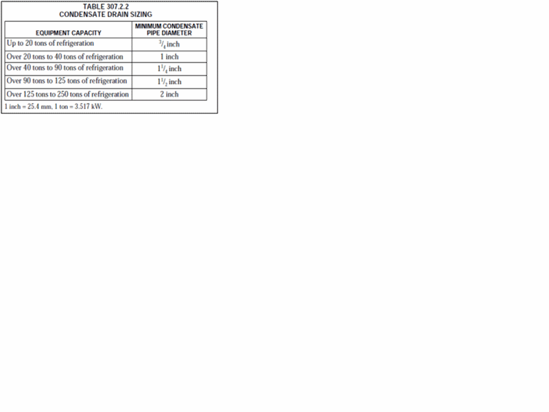
504.6.5 Length identification. Where the exhaust duct is concealed within the building construction, the equivalent length of the exhaust duct shall be identified on a permanent label or tag. The label or tag shall be located within 6 feet (1829 mm) of the exhaust duct connection.
504.6.6 Exhaust duct required. Where space for a clothes dryer is provided, an exhaust duct system shall be installed. Where the clothes dryer is not installed at the time of occupancy, the exhaust duct shall be capped at the location of the future dryer.
Exception: Where a listed condensing clothes dryer is installed prior to occupancy of structure.
(( 504.6.7 Protection required. Protective shield plates shall be placed where nails or screws from finish or other work are likely to penetrate the clothes dryer exhaust duct. Shield plates shall be placed on the finished face of all
framing members where there is less than 1-1/4 inches (32 mm) between the duct and the finished face of the framing member. Protective shield plates shall be constructed of steel, have a thickness of 0.062 inch (1.6 mm) and extend a minimum of 2 inches
(51 mm) above sole plates and below top plates.
504.7 Commercial clothes dryers. The installation of dryer exhaust ducts serving commercial clothes dryers shall comply with the appliance manufacturer's installation instructions. Exhaust fan motors installed in exhaust systems shall be located outside of the airstream. In multiple installations, the fan shall operate continuously or be interlocked to operate when any individual unit is operating. Ducts shall have a minimum clearance of 6 inches (152 mm) to combustible materials. Clothes dryer transition ducts used to connect the appliance to the exhaust duct system shall be limited to single lengths not to exceed 8 feet (2438 mm) in length and shall be listed and labeled for the application. Transition ducts shall not be concealed within construction.
[W] 504.7.1 Protection required. Protective shield plates shall be provided in accordance with Section 504.2.1.
504.8 Common exhaust systems for clothes dryers located in multistory structures. Where a common multistory duct system is designed and installed to convey exhaust from multiple clothes dryers, the construction of the system shall be in accordance with all of the following:
1. The shaft in which the duct is installed shall be constructed and fire-resistance rated as required by the International Building Code.
2. Dampers shall be prohibited in the exhaust duct. Penetrations of the shaft and ductwork shall be protected in accordance with Section 607.5.5, Exception 2.
3. Rigid metal ductwork shall be installed within the shaft to convey the exhaust. The ductwork shall be constructed of sheet steel having a minimum thickness of 0.0187 inch (0.4712 mm) (No. 26 gage) and in accordance with SMACNA Duct Construction Standards.
4. The ductwork within the shaft shall be designed and installed without offsets.
5. The exhaust fan motor design shall be in accordance with Section 503.2.
6. The exhaust fan motor shall be located outside of the airstream.
7. The exhaust fan shall run continuously, and shall be connected to a legally required standby power source.
8. Exhaust fan operation shall be monitored in an approved location and shall initiate an audible or visual signal when the fan is not in operation.
[W] 9. Makeup air shall be provided for the exhaust system to maintain the minimum flow for the exhaust fan when the dryers are not operating. Additionally, makeup air shall be provided when required by Section 504.5 .
10. A cleanout opening shall be located at the base of the shaft to provide access to the duct to allow for cleaning and inspection. The finished opening shall be not less than 12 inches by 12 inches (305 mm by 305 mm).
11. Screens shall not be installed at the termination.
12. The common multistory duct system shall serve only clothes dryers and shall be independent of other exhaust systems.
SECTION 505
DOMESTIC KITCHEN EXHAUST EQUIPMENT
[W] 505.1 Domestic systems. Where domestic range hoods and domestic appliances equipped with downdraft exhaust are located within dwelling units, such hoods and appliances shall discharge to the outdoors through sheet metal ducts constructed of galvanized steel, stainless steel, aluminum or copper. Such ducts shall have smooth inner walls, shall be air tight, shall be equipped with a backdraft damper, and shall be independent of all other exhaust systems.
Listed and labeled exhaust booster fans shall be permitted when installed in accordance with the manufacturer's installation instructions.
Exceptions:
1. Where installed in accordance with the manufacturer's installation instructions and where mechanical (( or natural ventilation
Interpretation : Chapter 4 requires separate local exhaust systems in kitchens, including where ductless range hoods (also known as recirculating hoods) are used. Ductless range hoods are permitted in dwelling units where exhaust systems in the kitchen meet the requirements for local exhaust. In no case is natural ventilation, such as an operable window, allowed to substitute for the required kitchen local exhaust system.
2. Ducts for domestic kitchen cooking appliances equipped with downdraft exhaust systems shall be permitted to be constructed of Schedule 40 PVC pipe and fittings provided that the installation complies with all of the following:
2.1. The duct shall be installed under a concrete slab poured on grade.
2.2. The underfloor trench in which the duct is installed shall be completely backfilled with sand or gravel.
2.3. The PVC duct shall extend not more than 1 inch (25 mm) above the indoor concrete floor surface.
2.4. The PVC duct shall extend not more than 1 inch (25 mm) above grade outside of the building.
2.5. The PVC ducts shall be solvent cemented.
***
SECTION 506
COMMERCIAL KITCHEN HOOD VENTILATION SYSTEM DUCTS AND EXHAUST EQUIPMENT
***
506.3 Ducts serving Type I hoods. Type I exhaust ducts shall be independent of all other exhaust systems except as provided in Section 506.3.5. Commercial kitchen duct systems serving Type I hoods shall be designed, constructed and installed in accordance with Sections 506.3.1 through 506.3.13.3.
506.3.1 Duct materials. Ducts serving Type I hoods shall be constructed of materials in accordance with Sections 506.3.1.1 and 506.3.1.2.
506.3.1.1 Grease duct materials. Grease ducts serving Type I hoods shall be constructed of steel having a minimum thickness of 0.0575 inch (1.463 mm) (No. 16 gage) or stainless steel not less than 0.0450 inch (1.14 mm) (No. 18 gage) in thickness.
Exception: Factory-built commercial kitchen grease ducts listed and labeled in accordance with UL 1978 and installed in accordance with Section 304.1.
506.3.1.2 Makeup air ducts. Makeup air ducts connecting to or within 18 inches (457 mm) of a Type I hood shall be constructed and installed in accordance with Sections 603.1, 603.3, 603.4, 603.9, 603.10 and 603.12. Duct insulation installed within 18 inches (457 mm) of a Type I hood shall be noncombustible or shall be listed for the application.
506.3.2 Joints, seams and penetrations of grease ducts. Joints, seams and penetrations of grease ducts shall be made with a continuous liquid-tight weld or braze made on the external surface of the duct system.
Exceptions:
1. Penetrations shall not be required to be welded or brazed where sealed by devices that are listed for the application.
2. Internal welding or brazing shall not be prohibited provided that the joint is formed or ground smooth and is provided with ready access for inspection.
3. Factory-built commercial kitchen grease ducts listed and labeled in accordance with UL 1978 and installed in accordance with Section 304.1.
506.3.2.1 Duct joint types. Duct joints shall be butt joints, welded flange joints with a maximum flange depth of 1/2 inch (12.7 mm) or overlapping duct joints of either the telescoping or bell type. Overlapping joints shall be installed to prevent ledges and obstructions from collecting grease or interfering with gravity drainage to the intended collection point. The difference between the inside cross-sectional dimensions of overlapping sections of duct shall not exceed 1/4 inch (6 mm). The length of overlap for overlapping duct joints shall not exceed 2 inches (51 mm).
506.3.2.2 Duct-to-hood joints. Duct-to-hood joints shall be made with continuous internal or external liquid-tight welded or brazed joints. Such joints shall be smooth, accessible for inspection, and without grease traps.
Exceptions: This section shall not apply to:
1. A vertical duct-to-hood collar connection made in the top plane of the hood in accordance with all of the following:
1.1. The hood duct opening shall have a 1-inch-deep (25 mm), full perimeter, welded flange turned down into the hood interior at an angle of 90 degrees (1.57 rad) from the plane of the opening.
1.2. The duct shall have a 1-inch-deep (25 mm) flange made by a 1-inch by 1-inch (25 mm by 25 mm) angle iron welded to the full perimeter of the duct not less than 1 inch (25 mm) above the bottom end of the duct.
1.3. A gasket rated for use at not less than 1,500 degrees F (815 degrees C) is installed between the duct flange and the top of the hood.
1.4. The duct-to-hood joint shall be secured by stud bolts not less than 1/4 inch (6.4 mm) in diameter welded to the hood with a spacing not greater than 4 inches (102 mm) on center for the full perimeter of the opening. All bolts and nuts are to be secured with lockwashers.
2. Listed and labeled duct-to-hood collar connections installed in accordance with Section 304.1.
506.3.2.3 Duct-to-exhaust fan connections. Duct-to-exhaust fan connections shall be flanged and gasketed at the base of the fan for vertical discharge fans; shall be flanged, gasketed and bolted to the inlet of the fan for side-inlet utility fans; and shall be flanged, gasketed and bolted to the inlet and outlet of the fan for in-line fans. Gasket and sealing materials shall be rated for continuous duty at a temperature of not less than 1500 degrees F (816 degrees C).
506.3.2.4 Vibration isolation. A vibration isolation connector for connecting a duct to a fan shall consist of noncombustible packing in a metal sleeve joint of approved design or shall be a coated-fabric flexible duct connector (( listed
and labeled for the application
506.3.2.5 Grease duct test. Prior to the use or concealment of any portion of a grease duct system, a leakage test shall be performed. Ducts shall be considered to be concealed where installed in shafts or covered by coatings or wraps that prevent the ductwork from being visually inspected on all sides. The permit holder shall be responsible to provide the necessary equipment and perform the grease duct leakage test. A light test shall be performed to determine that all welded and brazed joints are liquid tight. A light test shall be performed by passing a lamp having a power rating of not less than 100 watts through the entire section of ductwork to be tested. The lamp shall be open so as to emit light equally in all directions perpendicular to the duct walls. A test shall be performed for the entire duct system, including the hoodto-duct connection. The duct work shall be permitted to be tested in sections, provided that every joint is tested. For listed factory-built grease ducts, this test shall be limited to duct joints assembled in the field and shall exclude factory welds.
506.3.3 Grease duct supports. Grease duct bracing and supports shall be of noncombustible material securely attached to the structure and designed to carry gravity and seismic loads within the stress limitations of the International Building Code. Bolts, screws, rivets and other mechanical fasteners shall not penetrate duct walls.
506.3.4 Air velocity. Grease duct systems serving a Type I hood shall be designed and installed to provide an air velocity within the duct system of not less than 500 feet per minute (2.5 m/s).
Exception: The velocity limitations shall not apply within duct transitions utilized to connect ducts to differently sized or shaped openings in hoods and fans, provided that such transitions do not exceed 3 feet (914 mm) in length and are designed to prevent the trapping of grease.
506.3.5 Separation of grease duct system. A separate grease duct system shall be provided for each Type I hood. (( A separate grease duct system is not required
1. All interconnected hoods are located within the same story.
2. All interconnected hoods are located within the same room or in adjoining rooms.
3. Interconnecting ducts do not penetrate assemblies required to be fire-resistance rated.
4. The grease duct system does not serve solid-fuel-fired appliances.
506.3.6 Grease duct clearances. Where enclosures are not required, grease duct systems and exhaust equipment serving a Type I hood shall have a clearance to combustible construction of not less than 18 inches (457 mm), and shall have a clearance to noncombustible construction and gypsum wallboard attached to noncombustible structures of not less than 3 inches (76 mm).
Exceptions:
1. Factory-built commercial kitchen grease ducts listed and labeled in accordance with UL 1978.
2. Listed and labeled exhaust equipment installed in accordance with Section 304.1.
3. Where commercial kitchen grease ducts are continuously covered on all sides with a listed and labeled field-applied grease duct enclosure material, system, product or method of construction specifically evaluated for such purpose in accordance with ASTM E 2336, the required clearance shall be in accordance with the listing of such material, system, product or method.
506.3.7 Prevention of grease accumulation in grease ducts. Duct systems serving a Type I hood shall be constructed and installed so that grease cannot collect in any portion thereof, and the system shall slope not less than one-fourth unit vertical in 12 units horizontal (2-percent slope) toward the hood or toward a grease reservoir designed and installed in accordance with Section 506.3.7.1. Where horizontal ducts exceed 75 feet (22 860 mm) in length, the slope shall be not less than one unit vertical in 12 units horizontal (8.3 percent slope).
506.3.7.1 Grease reservoirs. Grease reservoirs shall:
1. Be constructed as required for the grease duct they serve.
2. Be located on the bottom of the horizontal duct or the bottommost section of the duct riser.
3. Have a length and width of not less than 12 inches (305 mm). Where the grease duct is less than 12 inches (305 mm) in a dimension, the reservoir shall be not more than 2 inches (51 mm) smaller than the duct in that dimension.
4. Have a depth of not less than 1 inch (25.4 mm).
5. Have a bottom that is sloped to a point for drainage.
6. Be provided with a cleanout opening constructed in accordance with Section 506.3.8 and installed to provide direct access to the reservoir. The cleanout opening shall be located on a side or on top of the duct so as to permit cleaning of the reservoir.
7. Be installed in accordance with the manufacturer's instructions where manufactured devices are utilized.
506.3.8 Grease duct cleanouts and openings. Grease duct cleanouts and openings shall comply with all of the following:
1. Grease ducts shall not have openings except where required for the operation and maintenance of the system.
2. Sections of grease ducts that are inaccessible from the hood or discharge openings shall be provided with cleanout openings.
3. Cleanouts and openings shall be equipped with tight-fitting doors constructed of steel having a thickness not less than that required for the duct.
4. Cleanout doors shall be installed liquid tight.
5. Door assemblies including any frames and gaskets shall be approved for the application and shall not have fasteners that penetrate the duct.
6. Gasket and sealing materials shall be rated for not less than 1500 degrees F (816 degrees C).
7. Listed door assemblies shall be installed in accordance with the manufacturer's instructions.
506.3.8.1 Personnel entry. Where ductwork is large enough to allow entry of personnel, not less than one approved or listed opening having dimensions not less than 22 inches by 20 inches (559 mm by 508 mm) shall be provided in the horizontal sections, and in the top of vertical risers. Where such entry is provided, the duct and its supports shall be capable of supporting the additional load, and the cleanouts specified in Section 506.3.8 are not required.
506.3.8.2 Cleanouts serving in-line fans. A cleanout shall be provided for both the inlet side and outlet side of an in-line fan except where a duct does not connect to the fan. Such cleanouts shall be located within 3 feet (914 mm) of the fan duct connections.
506.3.9 Grease duct cleanout location, spacing and installation.
506.3.9.1 Grease duct horizontal cleanouts. Cleanouts serving horizontal sections of grease ducts shall:
1. Be spaced not more than 20 feet (6096 mm) apart.
2. Be located not more than 10 feet (3048 mm) from changes in direction that are greater than 45 degrees (.79 rad).
3. Be located on the bottom only where other locations are not available and shall be provided with internal damming of the opening such that grease will flow past the opening without pooling. Bottom cleanouts and openings shall be approved for the application and installed liquid-tight.
4. Not be closer than 1 inch (25.4 mm) from the edges of the duct.
5. Have opening dimensions of not less than 12 inches by 12 inches (305 mm by 305 mm). Where such dimensions preclude installation, the opening shall be not less than 12 inches (305 mm) on one side and shall be large enough to provide access for cleaning and maintenance.
6. Shall be located at grease reservoirs.
506.3.9.2 Grease duct vertical cleanouts. Where ducts pass vertically through floors, cleanouts shall be provided. A minimum of one cleanout shall be provided on each floor. Cleanout openings shall be not less than 1-1/2 inches (38 mm) from all outside edges of the duct or welded seams. The opening minimum dimensions shall be 12 inches (305 mm) on each side.
506.3.10 Underground grease duct installation. Underground grease duct installations shall comply with all of the following:
1. Underground grease ducts shall be constructed of steel having a minimum thickness of 0.0575 inch (1.463 mm) (No. 16 gage) and shall be coated to provide protection from corrosion or shall be constructed of stainless steel having a minimum thickness of 0.0450 inch (1.140 mm) (No. 18 gage).
2. The underground duct system shall be tested and approved in accordance with Section 506.3.2.5 prior to coating or placement in the ground.
3. The underground duct system shall be completely encased in concrete with a minimum thickness of 4 inches (102 mm).
4. Ducts shall slope toward grease reservoirs.
5. A grease reservoir with a clean out to allow cleaning of the reservoir shall be provided at the base of each vertical duct riser.
6. Cleanouts shall be provided with access to permit cleaning and inspection of the duct in accordance with Section 506.3.
7. Cleanouts in horizontal ducts shall be installed on the topside of the duct.
8. Cleanout locations shall be legibly identified at the point of access from the interior space.
[W] 506.3.11 Grease duct enclosures. A grease duct serving a Type I hood that penetrates a ceiling, wall, floor or any concealed spaces shall be enclosed from the point of penetration to the outlet terminal. A duct shall penetrate exterior
walls only at locations where unprotected openings are permitted by the International Building Code . The duct enclosure shall serve a single grease duct and shall not contain other ducts, piping or wiring systems. Duct enclosures shall be either
field-applied or factory-built. Duct enclosures shall have a fire-resistance rating of not less than that of the assembly penetrated. The duct enclosure need not exceed 2 hours but shall be (( and
506.3.11.1 Shaft enclosure. Commercial kitchen grease ducts constructed in accordance with Section 506.3.1 shall be permitted to be enclosed in accordance with theInternational Building Code requirements for shaft construction. Such grease duct systems and exhaust equipment shall have a clearance to combustible construction of not less than 18 inches (457 mm), and shall have a clearance to noncombustible construction and gypsum wallboard attached to noncombustible structures of not less than 6 inches (76 mm). Duct enclosures shall be sealed around the duct at the point of penetration and vented to the outside of the building through the use of weather-protected openings.
Interpretation: Gypsum wallboard installed on a combustible substrate or on wood studs does not cause the wall to be considered as a noncombustible assembly, and the 18 inch minimum clearance still applies. The classification of combustible and noncombustible materials is not changed by the use of fire-retardant-treated wood products or fire rated (Type "X") gypsum wallboard.
506.3.11.2 Field-applied grease duct enclosure. Commercial kitchen grease ducts constructed in accordance with Section 506.3.1 shall be enclosed by field-applied grease duct enclosure that is a listed and labeled material, system, product, or method of construction specifically evaluated for such purpose in accordance with ASTM E 2336.
The surface of the duct shall be continuously covered on all sides from the point at which the duct originates to the outlet terminal. Duct penetrations shall be protected with a through-penetration fire-stop system classified in accordance with ASTM E 814 or UL 1497 and having a "F" and "T" rating equal to the fire-resistance rating of the assembly being penetrated. Such systems shall be installed in accordance with the listing and the manufacturer's installation instructions. Partial application of a field-applied grease duct enclosure system shall not be installed for the sole purpose of reducing clearances to combustibles at isolated sections of grease duct. Exposed duct-wrap systems shall be protected where subject to physical damage.
506.3.11.3 Factory-built grease duct assemblies. Factory-built grease duct assemblies incorporating integral enclosure materials shall be listed and labeled for use as commercial kitchen grease duct assemblies in accordance with UL 2221. Duct penetrations shall be protected with a throughpenetration firestop system classified in accordance with ASTM E 814 or UL 1479 and having an "F" and "T" rating equal to the fire-resistance rating of the assembly being penetrated. Such assemblies shall be installed in accordance with the listing and the manufacturer's installation instructions.
506.3.11.4 Duct enclosure not required. A duct enclosure shall not be required for a grease duct that penetrates only a nonfire-resistance-rated roof/ceiling assembly.
506.3.12 Grease duct fire-resistive access opening. Where cleanout openings are located in ducts within a fireresistance-rated enclosure, access openings shall be provided in the enclosure at each cleanout point. Access openings shall be equipped with tight-fitting sliding or hinged doors that are equal in fire-resistive protection to that of the shaft or enclosure. An approved sign shall be placed on access opening panels with wording as follows: "ACCESS PANEL. DO NOT OBSTRUCT."
506.3.13 Exhaust outlets serving Type I hoods. Exhaust outlets for grease ducts serving Type I hoods shall conform to the requirements of Sections 506.3.13.1 through 506.3.13.3.
506.3.13.1 Termination above the roof. Exhaust outlets that terminate above the roof shall have the discharge opening located not less than 40 inches (1016 mm) above the roof surface.
506.3.13.2 Termination through an exterior wall. Exhaust outlets shall be permitted to terminate through exterior walls where the smoke, grease, gases, vapors and odors in the discharge from such terminations do not create a public nuisance or a fire
hazard. Such terminations shall not be located where protected openings are required by the International Building Code. Other exterior openings shall not be located within (( 3 914
Note: See Director's Rule 6-2005, or any rule superseding Director's Rule 6-2005 for additional requirements.
506.3.13.3 Termination location. Exhaust outlets shall be located not less than 10 feet (3048 mm) horizontally from parts of the same or contiguous buildings, adjacent buildings and adjacent property lines and shall be located not less than 10 feet (3048 mm) above the adjoining grade level. Exhaust outlets shall be located not less than 10 feet (3048 mm) horizontally from or not less than 3 feet (914 mm) above air intake openings into any building.
Exception: Exhaust outlets shall terminate not less than 5 feet (1524 mm) horizontally from parts of the same or contiguous building, an adjacent building, adjacent property line and air intake openings into a building where air from the exhaust outlet discharges away from such locations.
Interpretation: For purposes of this section, property line includes any property line separating one lot from another lot, but does not include any property line separating a lot from a public street or alley right-of-way.
506.4 Ducts serving Type II hoods. Commercial kitchen exhaust systems serving Type II hoods shall comply with Sections 506.4.1 and 506.4.2.
506.4.1 Ducts. Ducts and plenums serving Type II hoods shall be constructed of rigid metallic materials. Duct construction, installation, bracing and supports shall comply with Chapter 6. A duct serving a Type II hood that penetrates a fireresistance-rated ceiling, floor or wall shall be enclosed in a duct enclosure from the point of penetration to the outlet terminal. Ducts subject to positive pressure and ducts conveying moisture-laden or waste-heat-laden air shall be constructed, joined and sealed in an approved manner.
506.4.2 Type II terminations. Exhaust outlets serving Type II hoods shall terminate in accordance with the hood manufacturer's installation instructions and shall comply with all of the following:
1. Exhaust outlets shall terminate not less than 3 feet (914 mm) in any direction from openings into the building.
2. Outlets shall terminate not less than 10 feet (3048 mm) from property lines or buildings on the same lot.
3. Outlets shall terminate not less than 10 feet (3048 mm) above grade.
4. Outlets that terminate above a roof shall terminate not less than 30 inches (762 mm) above the roof surface.
5. Outlets shall terminate not less than 30 inches (762 mm) from exterior vertical walls
6. Outlets shall be protected against local weather conditions.
7. Outlets shall not be directed onto walkways.
8. Outlets shall meet the provisions for exterior wall opening protectives in accordance with the International Building Code.
***
SECTION 507
COMMERCIAL KITCHEN HOODS
507.1 General. Commercial kitchen exhaust hoods shall comply with the requirements of this section. Hoods shall be Type I or II and shall be designed to capture and confine cooking vapors and residues. Commercial kitchen exhaust hood systems shall operate during the cooking operation.
Exceptions:
1. Factory-built commercial exhaust hoods that are listed and labeled in accordance with UL 710, and installed in accordance with Section 304.1 shall not be required to comply with Sections 507.4, 507.5, 507.7, 507.11, 507.12, 507.13, 507.14, and 507.15.
2. Factory-built commercial cooking recirculating systems that are listed and labeled in accordance with UL 710B, and installed in accordance with Section 304.1 shall not be required to comply with Sections 507.4, 507.5, 507.7, 507.11, 507.12, 507.13, 507.14, and 507.15. Spaces in which such systems are located shall be considered to be kitchens and shall be ventilated in accordance with Table 403.3. The kitchen exhaust system shall discharge in accordance with Section 501.3.1, item 3. For the purpose of determining the floor area required to be ventilated, each individual appliance shall be considered as occupying not less than 100 square feet (9.3 m2).
3. Net exhaust volumes for hoods shall be permitted to be reduced during part-load cooking conditions, where engineered or listed multispeed or variable-speed controls automatically operate the exhaust system to maintain capture and removal of cooking effluents as required by this section. Reduced volumes shall not be below that required to maintain capture and removal of effluents from the idle cooking appliances that are operating in a standby mode.
507.2 Where required. A Type I or Type II hood shall be installed at or above all commercial cooking appliances in accordance with Sections 507.2.1 and 507.2.2 and Table 507.2.1 . Where any cooking appliance under a single hood requires a Type I hood, a Type I hood shall be installed. Where a Type II hood is required, a Type I or Type II hood shall be installed.
Exception: Where cooking appliances are equipped with integral down-draft exhaust systems and such appliances and exhaust systems are listed and labeled for the application in accordance with NFPA 96, a hood shall not be required at or above them.
507.2.1 Type I hoods. Type I hoods shall be installed where cooking appliances produce grease or smoke as a result of the cooking process. Type I hoods shall be installed over mediumduty, heavy-duty and extra-heavy-duty cooking appliances. Type I hoods shall be installed over light-duty cooking appliances that produce grease or smoke.
Exception s :
1. A Type I hood shall not be required for an electric cooking appliance where an approved testing agency provides documentation that the appliance effluent contains 5 mg/m 3 or less of grease when tested at an exhaust flow rate of 500 cfm (0.236 m 3 /s) in accordance with Section 17 of UL 710B.
[W] 2. A Type I hood is not required in R-2 occupancies with not more than 16 residents.
507.2.1.1 Operation. Type I hood systems shall be designed and installed to automatically activate the exhaust fan whenever cooking operations occur. The activation of the exhaust fan shall occur through an interlock with the cooking appliances, by means of heat sensors or by means of other approved methods. A method of interlock between an exhaust hood system and appliances equipped with standing pilot burners shall not cause the pilot burners to be extinguished. A method of interlock between an exhaust hood system and cooking appliances shall not involve or depend upon any component of a fire extinguishing system.
507.2.1.2 Exhaust flow rate label. Type I hoods shall bear a label indicating the minimum exhaust flow rate in cfm per linear foot (1.55 L/s per linear meter) of hood that provides for capture and containment of the exhaust effluent for the cooking appliances served by the hood, based on the cooking appliance duty classifications defined in this code.
507.2.2 Type II hoods. Type II hoods shall be installed for collecting and removing steam, vapor, heat or odors from (( above above
507.2.3 Domestic cooking appliances used for commercial purposes. Domestic cooking appliances utilized for commercial purposes shall be provided with Type I , (( or as required for the type of appliances and processes
507.2.4 Extra-heavy-duty. Type I hoods for use over extraheavy-duty cooking appliances shall not cover heavy-, mediumor light-duty appliances. Such hoods shall discharge to an exhaust system that is independent of other exhaust systems.
Note: The definition of extra-heavy-duty cooking appliance includes appliances using solid fuel.
| [W] Table 507.2.1 Type of Hood Required for Commercial Cooking Appliances |
||||||||||||||||||||||||||||||||||||||||||||||||||||||||||||||||||||||||||||||||||||||||||||||||||||||||||||||||||||||||||||||||||||||||||||||||||||||||||||||||||||||||||||||
|
*** 507.13 Capacity of hoods. Commercial food service hoods shall exhaust a minimum net quantity of air determined in accordance with this section and Sections 507.13.1 through 507.13.5. The net quantity of exhaust air shall be calculated by subtracting any airflow supplied directly to a hood cavity from the total exhaust flow rate of a hood. Where any combination of heavyduty, medium-duty and light-duty cooking appliances are utilized under a single hood, the exhaust rate required by this section for the heaviest duty appliance covered by the hood shall be used for the entire hood. 507.13.1 Extra-heavy-duty (solid fuel) cooking appliances. The minimum net airflow for hoods, as determined by Section 507.2, used for extra-heavy-duty cooking appliances shall be determined as follows:
For SI: 1 cfm per linear foot = 1.55 L/s per linear meter. *** SECTION 508 COMMERCIAL KITCHEN MAKEUP AIR
508.1 Makeup air. Makeup air shall be supplied during the operation of commercial kitchen exhaust systems that are provided for commercial cooking appliances. (( Exceptions: 1. Where the total airflow for the exhaust system is less than 400 cfm, makeup air is not required; or 2. In atriums, food courts, and similar areas, occupant ventilation air that would otherwise exfiltrate or be exhausted by other mechanical exhaust systems may be used to provide all makeup air, or a portion of makeup air when a direct path through permanent openings exists for occupant ventilation air to transfer to the kitchen hood area. That portion of air not supplied by occupant ventilation air shall be provided by a separate makeup air system. The combined air quantity provided by a separate makeup air system and occupant ventilation air shall provide 100 percent of the air to be exhausted. 508.1.1 Makeup air temperature. The temperature differential between makeup air and the air in the conditioned space shall not exceed 10 degrees F (6 degrees C) if the amount of makeup air supply exceeds 2,500 cfm (1180 L/s) per space except where the added heating and cooling loads of the makeup air do not exceed the capacity of the HVAC system. *** SECTION 510 HAZARDOUS EXHAUST SYSTEMS *** 510.2 Where required. A hazardous exhaust system shall be required wherever operations involving the handling or processing of hazardous materials, in the absence of such exhaust systems and under normal operating conditions, have the potential to create one of the following conditions: 1. A flammable vapor, gas, fume, mist or dust is present in concentrations exceeding 25 percent of the lower flammability limit of the substance for the expected room temperature. 2. A vapor, gas, fume, mist or dust with a health-hazard rating of 4 is present in any concentration. 3. A vapor, gas, fume, mist or dust with a health-hazard rating of 1, 2 or 3 is present in concentrations exceeding 1 percent of the median lethal concentration of the substance for acute inhalation toxicity.
(( In lieu of complying with this section, research and educational laboratories are permitted to comply with rules adopted by the Director for laboratory exhaust systems for hazardous materials. Note: See Director's Rule 30-2005, or any rule superseding Director's Rule 30-2005 for alternate provisions for research and education laboratories. [F] 510.2.1 Lumber yards and woodworking facilities. Equipment or machinery located inside buildings at lumber yards and woodworking facilities which generates or emits combustible dust shall be provided with an approved dust-collection and exhaust system installed in conformance with this section and the International Fire Code. Equipment and systems that are used to collect, process or convey combustible dusts shall be provided with an approved explosion-control system. [F] 510.2.2 Combustible fibers. Equipment or machinery within a building which generates or emits combustible fibers shall be provided with an approved dust-collecting and exhaust system. Such systems shall comply with this code and the International Fire Code. 510.2.3 Model shops and other intermittent use facilities. Equipment or machinery located inside buildings that emit dust but are used on an intermittent basis, such as in model shops, research and development facilities, hobby, and other nonproduction uses, shall be provided with a local, point of use dust collection system. The dust collector is permitted to be a portable type with high efficiency filters to allow exhaust air to be discharged back into the space. Such collectors are not required to be provided with an approved explosion-control system. Such systems shall be limited to an aggregate airflow of no more than 1,500 cfm per room. *** 510.7 Suppression required. 510.7.1 Ducts. Ducts shall be protected with an approved automatic fire suppression system installed in accordance with the International Building Code. Exceptions: 1. An approved automatic fire suppression system shall not be required in ducts conveying materials, fumes, mists and vapors that are nonflammable and noncombustible under all conditions and at any concentrations. 2. Automatic fire suppression systems shall not be required in metallic and noncombustible, nonmetallic exhaust ducts in semiconductor fabrication facilities. 3. An approved automatic fire suppression system shall not be required in ducts where the largest cross-sectional diameter of the duct is less than 10 inches (254 mm).
4. For laboratories, as defined in Section 510.1, automatic fire protection systems shall not be required for metallic ducts that serve (( 5. An approved automatic fire suppression system is not required in metallic ducts serving fume hoods if all fume hoods served by the duct are equipped with an approved fire suppression system. 510.7.2 Fume hoods. Approved automatic fire suppression shall be installed in fume hoods within which operations are conducted involving hazardous materials that have the potential to create a flammable vapor, gas, fume, mist, or dust in concentrations exceeding 25 percent of the lower flammability limit of the substance or mixture for the expected room temperature in the absence of the fume hood and under normal operating conditions. *** SECTION 511 DUST, STOCK AND REFUSE CONVEYING SYSTEMS 511.1 Dust, stock and refuse conveying systems. Dust, stock and refuse conveying systems shall comply with the provisions of Section 510 and Sections 511.1.1 through 511.2. 511.1.1 Collectors and separators. Collectors and separators involving such systems as centrifugal separators, bag filter systems and similar devices, and associated supports shall be constructed of noncombustible materials and shall be located on the exterior of the building or structure. A collector or separator shall not be located nearer than 10 feet (3048 mm) to combustible construction or to an unprotected wall or floor opening, unless the collector is provided with a metal vent pipe that extends above the highest part of any roof with a distance of 30 feet (9144 mm). Exceptions: 1. Collectors such as "Point of Use" collectors, close extraction weld fume collectors, spray finishing booths, stationary grinding tables, sanding booths, and integrated or machine-mounted collectors shall be permitted to be installed indoors provided the installation is in accordance with the International Fire Code and NFPA 70.
2. Collectors in independent exhaust systems handling combustible dusts shall be permitted to be installed indoors provided that such collectors are installed in compliance with the International Fire Code and (( 511.1.2 Discharge pipe. Discharge piping shall conform to the requirements for ducts, including clearances required for high-heat appliances, as contained in this code. A delivery pipe from a cyclone collector shall not convey refuse directly into the firebox of a boiler, furnace, dutch oven, refuse burner, incinerator or other appliance. 511.1.3 Conveying systems exhaust discharge. An exhaust system shall discharge to the outside of the building either directly by flue or indirectly through the bin or vault into which the system discharges except where the contaminants have been removed. Exhaust system discharge shall be permitted to be recirculated provided that the solid particulate has been removed at a minimum efficiency of 99.9 percent at 10 microns (10.01 mm), vapor concentrations are less than 25 percent of the LFL, and approved equipment is used to monitor the vapor concentration. 511.1.4 Spark protection. The outlet of an open-air exhaust terminal shall be protected with an approved metal or other noncombustible screen to prevent the entry of sparks. 511.1.5 Explosion relief vents. A safety or explosion relief vent shall be provided on all systems that convey combustible refuse or stock of an explosive nature, in accordance with the requirements of the International Building Code. 511.1.5.1 Screens. Where a screen is installed in a safety relief vent, the screen shall be attached so as to permit ready release under the explosion pressure. 511.1.5.2 Hoods. The relief vent shall be provided with an approved noncombustible cowl or hood, or with a counterbalanced relief valve or cover arranged to prevent the escape of hazardous materials, gases or liquids. *** SECTION 512 SUBSLAB SOIL EXHAUST SYSTEMS ***
512.2 Materials. Subslab soil exhaust system duct material shall be air duct material listed and labeled to the requirements of UL 181 for Class 0 air ducts, or any of the following piping materials that comply with the (( *** SECTION 513 SMOKE CONTROL SYSTEMS *** [F] 513.3 Special inspection and test requirements. In addition to the ordinary inspection and test requirements which buildings, structures and parts thereof are required to undergo, smoke control systems subject to the provisions of Section 909 of the International Building Code shall undergo special inspections and tests sufficient to verify the proper commissioning of the smoke control design in its final installed condition. The design submission accompanying the construction documents shall clearly detail procedures and methods to be used and the items subject to such inspections and tests. Such commissioning shall be in accordance with generally accepted engineering practice and, where possible, based on published standards for the particular testing involved. The special inspections and tests required by this section shall be conducted under the same terms as found in Section 1704 of the International Building Code. Note: See SFD Administrative Rules 9.01.13 and 9.02.09 or any rule superseding them for further specific requirements. ***
[F] 513.11 Power systems. The smoke control system shall be supplied with two sources of power. Primary power shall be the normal building power systems. Secondary power shall be from an approved (( Exception: A separate room for the generator set is not required for systems having fixed fuel quantities meeting the limits of International Fire Code Section 603.3 when located in a sprinklered parking garage of Type I or II construction [F] 513.11.1 Power sources and power surges. Elements of the smoke management system relying on volatile memories or the like shall be supplied with uninterruptible power sources of sufficient duration to span 15-minute primary power interruption. Elements of the smoke management system susceptible to power surges shall be suitably protected by conditioners, suppressors or other approved means. [F] 513.11.2 Wiring. In addition to meeting requirements of the Seattle Electrical Code, all wiring regardless of voltage, shall have fire-resistance-rated protection of at least two hours or as required in rules promulgated by the code official. Exception: Subject to the approval of the code official, fire-resistance-rating is not required for wiring located in a parking garage. [F] 513.12 Detection and control systems. Fire detection systems providing control input or output signals to mechanical smoke control systems or elements thereof shall comply with NFPA 72 and the requirements of Chapter 9 of the International Building Code or the International Fire Code. Such systems shall be equipped with a control unit complying with UL 864 and listed as smoke control equipment. Control systems for mechanical smoke control systems shall include provisions for verification. Verification shall include positive confirmation of actuation, testing, manual override, the presence of power downstream of all disconnects and, through a preprogrammed weekly test sequence report, abnormal conditions audibly, visually and by printed report.
[F] 513.12.1 Wiring. (( [F] 513.12.2 Activation. Smoke control systems shall be activated in accordance with the International Building Code or the International Fire Code.
[F] 513.12.3 Automatic control. Where completely automatic control is required or used, the automatic control sequences shall be initiated from an appropriately zoned automatic sprinkler system complying with Section 903.3.1.1 of the International Fire
Code or from manual controls that are readily accessible to the fire department, and any smoke detectors in the building (( *** Section 7. The following sections of Chapter 6 of the International Mechanical Code, 2012 Edition, are amended as follows: CHAPTER 6 DUCT SYSTEMS SECTION 601 GENERAL *** [B] 601.2 Air movement in egress elements. Corridors shall not serve as supply, return, exhaust, relief or ventilation air ducts. Exceptions:
1. Use of a corridor as a source of makeup air for exhaust systems in rooms that open directly onto such corridors, including toilet rooms, bathrooms, dressing rooms, (( 2. Where located within a dwelling unit, the use of corridors for conveying return air shall not be prohibited. 3. Where located within tenant spaces of 1,000 square feet (93 m 2 ) or less in area, use of corridors for conveying return air is permitted. 4. Incidental air movement from pressurized rooms within health care facilities, provided that the corridor is not the primary source of supply or return to the room. [W] 5. Where such air is part of an engineered smoke control system. [W] 6. Air supplied to corridors serving residential occupancies shall not be considered as providing ventilation air to the dwelling units subject to the following: 6.1 The air supplied to the corridor is one hundred percent outside air; and 6.2 The dwelling units have conforming ventilation air independent of the air supplied to the corridor; and 6.3 For other than high-rise buildings, the supply fan will automatically shut off upon activation of corridor smoke detectors which shall be spaced at no more than 30 feet (9144 mm) on center along the corridor; or 6.4 For high-rise buildings, the supply fan will automatically shut off upon activation of the smoke detectors required by Seattle Fire Code Section 907.2.13.1 or upon receipt of another approved fire alarm signal. The supply fan is not required to be automatically shut off when used as part of an approved building stairwell or elevator hoistway pressurization system. [B] 601.2.1 Corridor ceiling. Use of the space between the corridor ceiling and the floor or roof structure above as a return air plenum is permitted for one or more of the following conditions: 1. The corridor is not required to be of fire-resistance-rated construction; 2. The corridor is separated from the plenum by fireresistance-rated construction; 3. The air-handling system serving the corridor is shut down upon activation of the air-handling unit smoke detectors required by this code; 4. The air-handling system serving the corridor is shut down upon detection of sprinkler waterflow where the building is equipped throughout with an automatic sprinkler system; or 5. The space between the corridor ceiling and the floor or roof structure above the corridor is used as a component of an approved engineered smoke control system. *** SECTION 602 PLENUMS *** 602.2 Construction. Plenum enclosures shall be constructed of materials permitted for the type of construction classification of the building. The use of gypsum boards to form plenums shall be limited to systems where the air temperatures do not exceed 125 degrees F (52 degrees C) and the building and mechanical system design conditions are such that the gypsum board surface temperature will be maintained above the airstream dew-point temperature as determined by the registered design professional . Air plenums formed by gypsum boards shall not be incorporated in air-handling systems utilizing evaporative coolers. 602.2.1 Materials within plenums. Except as required by Sections 602.2.1.1 through 602.2.1.5, materials within plenums shall be noncombustible or shall be listed and labeled as having a flame spread index of not more than 25 and a smokedeveloped index of not more than 50 when tested in accordance with ASTM E 84 or UL 723. Exceptions: 1. Rigid and flexible ducts and connectors shall conform to Section 603. 2. Duct coverings, linings, tape and connectors shall conform to Sections 603 and 604. 3. This section shall not apply to materials exposed within plenums in oneand two-family dwellings. 4. This section shall not apply to smoke detectors. 5. Combustible materials fully enclosed within one of the following: 5.1. Continuous noncombustible raceways or enclosures. 5.2. Approved gypsum board assemblies. 5.3. Materials listed and labeled for installation within a plenum. 6. Materials in Group H, Division 5 fabrication areas and the areas above and below the fabrication area that share a common air recirculation path with the fabrication area.
602.2.1.1 Wiring. Combustible electrical wires and cables and optical fiber cables exposed within a plenum shall be listed as having a maximum peak optical density of 0.50 or less, an average optical density of 0.15 or less, and a maximum flame spread
distance of 5 feet (1524 mm) or less when tested in accordance with NFPA 262 or shall be installed in metal raceways or metal sheathed cable. Combustible optical fiber and communication raceways exposed within a plenum shall be listed as having a
maximum peak optical density of 0.5 or less, an average optical density of 0.15 or less, and a maximum flame spread distance of 5 feet (1524 mm) or less when tested in accordance with ANSI/UL 2024. Only plenum-rated wires and cables shall be installed
in plenum-rated raceways. Electrical wires and cables, optical fiber cables and raceways addressed in this section shall be listed and labeled and shall be installed in accordance with the Seattle Electrical Code (( 602.2.1.2 Fire sprinkler piping. Plastic fire sprinkler piping exposed within a plenum shall be used only in wet pipe systems and shall have a peak optical density not greater than 0.50, an average optical density not greater than 0.15, and a flame spread of not greater than 5 feet (1524 mm) when tested in accordance with UL 1887. Piping shall be listed and labeled. 602.2.1.3 Pneumatic tubing. Combustible pneumatic tubing exposed within a plenum shall have a peak optical density not greater than 0.50, an average optical density not greater than 0.15, and a flame spread of not greater than 5 feet (1524 mm) when tested in accordance with UL 1820. Combustible pneumatic tubing shall be listed and labeled. 602.2.1.4 Electrical equipment in plenums. Electrical equipment exposed within a plenum shall comply with Sections 602.2.1.4.1 and 602.2.1.4.2. 602.2.1.4.1 Equipment in metallic enclosures. Electrical equipment with metallic enclosures exposed within a plenum shall be permitted. 602.2.1.4.2 Equipment in combustible enclosures. Electrical equipment with combustible enclosures exposed within a plenum shall be listed and labeled for such use in accordance with UL 2043. 602.2.1.5 Foam plastic insulation. Foam plastic insulation used as interior wall or ceiling finish, or as interior trim, in plenums shall exhibit a flame spread index of 75 or less and a smoke-developed index of 450 or less when tested in accordance with ASTM E 84 or UL 723 and shall also comply with one or more of Sections 602.2.1.5.1, 602.2.1.5.2 and 602.2.1.5.3. 602.2.1.5.1 Separation required. The foam plastic insulation shall be separated from the plenum by a thermal barrier complying with Section 2603.4 of the International Building Code and shall exhibit a flame spread index of 75 or less and a smoke-developed index of 450 or less when tested in accordance with ASTM E 84 or UL 723 at the thickness and density intended for use. 602.2.1.5.2 Approval. The foam plastic insulation shall exhibit a flame spread index of 25 or less and a smokedeveloped index of 50 or less when tested in accordance with ASTM E 84 or UL 723 at the thickness and density intended for use and shall meet the acceptance criteria of Section 803.1.2 of the International Building Code when tested in accordance with NFPA 286. The foam plastic insulation shall be approved based on tests conducted in accordance with Section 2603.10 of the International Building Code. 602.2.1.5.3 Covering. The foam plastic insulation shall be covered by corrosion-resistant steel having a base metal thickness of not less than 0.0160 inch (0.4 mm) and shall exhibit a flame spread index of 75 or less and a smokedeveloped index of 450 or less when tested in accordance with ASTM E 84 or UL 723 at the thickness and density intended for use. *** SECTION 603 DUCT CONSTRUCTION AND INSTALLATION *** 603.5 Nonmetallic ducts. Nonmetallic ducts shall be constructed with Class 0 or Class 1 duct material and shall comply with UL 181. Fibrous duct construction shall conform to the SMACNA Fibrous Glass Duct Construction Standards or NAIMA Fibrous Glass Duct Construction Standards. The air temperature within nonmetallic ducts shall not exceed 250 degrees F (121 degrees C). 603.5.1 Gypsum ducts. The use of gypsum boards to form air shafts (ducts) shall be limited to return air systems where the air temperatures do not exceed 125 degrees F (52 degrees C) and the gypsum board surface temperature is maintained above the airstream dew-point temperature as determined by the registered design professional . Air ducts formed by gypsum boards shall not be incorporated in air-handling systems utilizing evaporative coolers. Exceptions: 1. Gypsum boards may be used for ducts that are only used for stairway or elevator pressurization supply air. The gypsum duct shall not attach directly to the equipment. 2. Gypsum boards coated on the inside with epoxy paint or foil-facing may be used for ventilation systems serving parking garages. 3. Gypsum boards coated on the inside with epoxy paint or foil-facing may be used for exhaust air ducts.
*** 603.10 Supports. Ducts shall be supported at intervals not to exceed 12 feet (3658 mm) and shall be in accordance with SMACNA HVAC Duct Construction Standards-Metal and Flexible. Flexible and other factory-made ducts shall be supported in accordance with the manufacturer's instructions. 603.10.1 Seismic loads. Bracing for ducts shall be designed to resist seismic loading, using accepted engineering practices and Chapter 16 of the International Building Code. Interpretation: Duct bracing that complies with the SMACNA guideline "Seismic Restraint Manual Guidelines for Mechanical Systems" is deemed to comply with Section 603.10 and the International Building Code. *** 603.14 Location. Ducts shall not be installed in or within 4 inches (102 mm) of the earth, except where such ducts comply with Section 603.8. Ducts installed in parking garages shall provide a clear floor height of not less than 6 feet 6 inches at the vehicle and pedestrian traffic areas, except where a minimum vertical clearance of 98 inches must be provided for required van-accessible parking spaces, access aisles serving them, and vehicular routes between the vanaccessible parking spaces and the garage entrance and exit. *** SECTION 605 AIR FILTERS *** [W] 605.4 Particulate matter removal. Particulate matter filters or air cleaners having a minimum efficiency reporting value (MERV) of not less than 6 for ducted air handlers and not less than 4 for unducted air handlers shall be provided upstream of all cooling coils or other devices with wetted surfaces through which air is supplied to an occupiable space. SECTION 606 SMOKE DETECTION SYSTEMS CONTROL *** 606.2 Where required. Smoke detectors shall be installed where indicated in Sections 606.2.1 through 606.2.3. Exception: Smoke detectors shall not be required where air distribution systems are incapable of spreading smoke beyond the enclosing walls, floors and ceilings of the room or space in which the smoke is generated. 606.2.1 Return air systems. Smoke detectors shall be installed in return air systems with a design capacity greater than 2,000 cfm (0.9 m 3 /s), in the return air duct or plenum upstream of any filters, exhaust air connections, outdoor air connections, or decontamination equipment and appliances. Exception: Smoke detectors are not required in the return air system where all portions of the building served by the air distribution system are protected by area smoke detectors connected to a fire alarm system in accordance with the International Fire Code. The area smoke detection system shall comply with Section 606.4. 606.2.2 Common supply and return air systems. Where multiple air-handling systems share common supply or return air ducts or plenums with a combined design capacity greater than 2,000 cfm (0.9 m 3 /s), the return air system shall be provided with smoke detectors in accordance with Section 606.2.1. Exception: Individual smoke detectors shall not be required for each fan-powered terminal unit, provided that such units do not have an individual design capacity greater than 2,000 cfm (0.9 m3/s) and will be shut down by activation of one of the following: 1. Smoke detectors required by Sections 601.2, 606.2.1 and 606.2.3. 2. An approved area smoke detector system located in the return air plenum serving such units. 3. An area smoke detector system as prescribed in the exception to Section 606.2.1. In all cases, the smoke detectors shall comply with Sections 606.4 and 606.4.1. The shutdown of fan-powered terminal units may be performed by a building automation system upon activation of smoke detection as described in Section 606.2.2, Exception Items 1, 2, or 3. The building automation system is not required to be listed as a smoke control system and is not required to comply with UL Standard 864: Standard for Control Units and Accessories for Fire Alarm Systems. 606.2.3 Return air risers. Where return air risers serve two or more stories and serve any portion of a return air system having a design capacity greater than 15,000 cfm (7.1 m3/s), smoke detectors shall be installed at each story. Such smoke detectors shall be located upstream of the connection between the return air riser and any air ducts or plenums. *** [F] 606.4 Controls operation. Upon activation, the smoke detectors shall shut down all operational capabilities of the air distribution system in accordance with the listing and labeling of appliances used in the system. Air distribution systems that are part of a smoke control system shall switch to the smoke control mode upon activation of a detector.
[F] 606.4.1 Supervision. The duct smoke detectors shall be connected to the building's fire alarm control unit (( Exceptions: 1. The supervisory signal at a constantly attended location is not required where the duct smoke detector activates the building's alarm-indicating appliances. 2. In occupancies not required to be equipped with a fire alarm system, actuation of a smoke detector shall activate a visible and audible signal in an approved location. Duct smoke detector trouble conditions shall activate a visible or audible signal in an approved location and shall be identified as air duct detector trouble. [B] SECTION 607 DUCT AND TRANSFER OPENINGS *** 607.3 Damper testing, ratings and actuation. Damper testing, ratings and actuation shall be in accordance with Sections 607.3.1 through 607.3.3. 607.3.1 Damper testing. Dampers shall be listed and labeled in accordance with the standards in this section. Fire dampers shall comply with the requirements of UL 555. Only fire dampers labeled for use in dynamic systems shall be installed in heating, ventilation and air-conditioning systems designed to operate with fans on during a fire. Smoke dampers shall comply with the requirements of UL 555S. Combination fire/smoke dampers shall comply with the requirements of both UL 555 and UL 555S. Ceiling radiation dampers shall comply with the requirements of UL 555C or shall be tested as part of a fire-resistance-rated floor/ceiling or roof/ceiling assembly in accordance with ASTM E119 or UL 263. 607.3.2 Damper rating. Damper ratings shall be in accordance with Sections 607.3.2.1 through 607.3.2.3. 607.3.2.1 Fire damper ratings. Fire dampers shall have the minimum fire protection rating specified in Table 607.3.2.1 for the type of penetration. TABLE 607.3.2.1 FIRE DAMPER RATING
FIGURE 703.2.1 Appliances Located in Confined Spaces All Air Taken from Inside the Building 703.2.1 Size of openings. Each opening shall have a free area of not less than 1 in.[2] per 1000 Btu/hr (140in.[2] per gal/hr) (22 cm[2]/kW), based on the total input rating of all appliances in the space. 703.2.2 Source of air. Each opening shall freely communicate with interior areas of the building that, in turn, have adequate infiltration from the outside. 703.3 All air taken from outdoors. Where all air will be taken from outdoors, the confined space shall be provided with two permanent openings, one near the top of the space and one in or near the bottom. 703.3.1 Source of air. The openings shall communicate directly or by means of ducts with the outdoors or to spaces such as an attic or crawl space, that themselves freely communicate with the outdoors, as shown in Figure 703.3.2.1, Figure 703.3.2.2, and Figure 703.3.2.3. 703.3.2 Vertical ducts. Where communicating with the outdoors directly or by means of vertical ducts, each opening shall have a free area of not less than 1 inch[2] per 4000 Btu/hr (35 inch[2] per gal/hr) (5.5 cm[2]/kW), based on the total input rating of all appliances in the space. 703.3.3 Horizontal ducts. Where communicating with the outdoors by means of horizontal ducts, each opening shall have a free area of not less than 1 inch[2] per 2000 Btu/hr (70 inch[2] per gal/hr) (11 cm[2]/kW), based on the total input rating of all appliances in the space.
FIGURE 703.3.2.1 Appliances Located in Confined
FIGURE 703.3.2.2 Appliances Located in Confined Spaces All Air from Outdoors Through Ventilated Attic
FIGURE 703.3.2.3 Appliances Located in Confined Spaces, with ventilation air from inside building and combustion air from outside, ventilated attic, or ventilated crawl space. 703.4 Ventilation air taken from inside the building-combustion air taken from outdoors. Where ventilation air will be taken from inside the building and combustion air will be taken from outdoors, the confined space shall be provided with two openings for ventilation, located and sized as specified in Section 703.2 and as shown in Figure 703.3.2.3. In addition, there shall be one opening communicating directly with the outdoors or to spaces, such as an attic or crawl space, that freely communicates with the outdoors and has a free area of not less than 1 in. 2 per 5000 Btu/hr (28 in. 2 per gal/hr) (4.4 cm/kW), based on the total input of all appliances in the space. Section 704 COMBUSTION AIR FOR COMMERCIAL AND INDUSTRIAL INSTALLATIONS 704.1 General. For commercial and industrial oilburning equipment, permanent means for supplying an ample amount of outside air shall be provided in accordance with this section. 704.2 Size of openings. For furnace or boiler rooms adjacent to outside walls and where combustion air is provided by natural ventilation from the outside, there shall be a permanent air supply inlet having a total free area of not less than 1 in. 2 per 4000 Btu/hr (35 in. 2 per gal/hr) (5.5 cm 2 /kW), based on the total input rating of the burner or burners, but in no case less than 35 in. 2 (0.425 m 2 ). For furnace or boiler rooms that are not adjacent to outside walls, the combustion air shall be supplied in a manner acceptable to the building official. Section 705 LOUVERS AND GRILLES 705.1 Louvers and grilles. In calculating the free area required by Sections 701, 702, 703 and 704, the blocking effect of louvers, grilles, or screens protecting openings shall be taken into consideration. 705.2 Screens. Screens used in louvers or grilles shall not be smaller than 1/4 in(6.3 mm) mesh and shall be accessible for cleaning. 705.3 Size of openings. If the free area through a particular design of louver or grille is known, it shall be used in calculating the size of the opening needed to provide the free area required. If the free area of the design is not known, it shall be assumed that wood louvers will have 20 percent to 25 percent free area and metal louvers and grilles will have 60 percent to 75 percent free area. Section 706 SPECIAL CONDITIONS 706.1 Special conditions. Where an appliance is installed in a location where the operation of exhaust fans, kitchen ventilation systems, clothes dryers or fireplaces can create conditions of unsatisfactory combustion or venting, special provisions shall be made subject to the approval of the building official. Section 9. The following sections of Chapter 8 of the International Mechanical Code, 2012 Edition, are amended as follows: CHAPTER 8 CHIMNEYS AND VENTS *** SECTION 804 DIRECT-VENT, INTEGRAL VENT AND MECHANICAL DRAFT SYSTEMS *** 804.3 Mechanical draft systems. Mechanical draft systems of either forced or induced draft design shall be listed and labeled in accordance with UL 378 and shall comply with Sections 804.3.1 through 804.3.7. 804.3.1 Forced draft systems. Forced draft systems and all portions of induced draft systems under positive pressure during operation shall be designed and installed so as to be gas tight to prevent leakage of combustion products into a building. 804.3.2 Automatic shutoff. Power exhausters serving automatically fired appliances shall be electrically connected to each appliance to prevent operation of the appliance when the power exhauster is not in operation. 804.3.3 Termination. The termination of chimneys or vents equipped with power exhausters shall be located a minimum of 10 feet (3048 mm) from the lot line or from adjacent buildings. The exhaust shall be directed away from the building. 804.3.4 Horizontal terminations. Horizontal terminations shall comply with the following requirements:
1. Where located adjacent to walkways, the termination of mechanical draft systems shall be not less than (( 2. Vents shall terminate at least 3 feet (914 mm) above any forced air inlet located within 10 feet (3048 mm). 3. The vent system shall terminate at least 4 feet (1219 mm) below, 4 feet (1219 mm) horizontally from or 1 foot (305 mm) above any door, window or gravity air inlet into the building. 4. The vent termination point shall not be located closer than 3 feet (914 mm) to an interior corner formed by two walls perpendicular to each other. 5. The vent termination shall not be mounted directly above or within 3 feet (914 mm) horizontally from an oil tank vent or gas meter. 6. The bottom of the vent termination shall be located at least 12 inches (305 mm) above finished grade. 804.3.5 Vertical terminations. Vertical terminations shall comply with the following requirements:
1. Where located adjacent to walkways, the termination of mechanical draft systems shall be not less than ((
2. Vents shall terminate at least 3 feet (914 mm) above any forced air inlet located within 10 feet (3048 mm) (( 3. Where the vent termination is located below an adjacent roof structure, the termination point shall be located at least 3 feet (914 mm) from such structure. 4. The vent shall terminate at least 4 feet (1219 mm) below, 4 feet (1219 mm) horizontally from or 1 foot (305 mm) above any door, window or gravity air inlet for the building. 5. A vent cap shall be installed to prevent rain from entering the vent system. 6. The vent termination shall be located at least 3 feet (914 mm) horizontally from any portion of the roof structure. 804.3.6 Exhauster connections. An appliance vented by natural draft shall not be connected into a vent, chimney or vent connector on the discharge side of a mechanical flue exhauster. 804.3.7 Exhauster sizing. Mechanical flue exhausters and the vent system served shall be sized and installed in accordance with the manufacturer's installation instructions. 804.3.8 Mechanical draft systems for manually fired appliances and fireplaces. A mechanical draft system shall be permitted to be used with manually fired appliances and fireplaces where such system complies with all of the following requirements: 1. The mechanical draft device shall be listed and labeled in accordance with UL 378, and shall be installed in accordance with the manufacturer's instructions. 2. A device shall be installed that produces visible and audible warning upon failure of the mechanical draft device or loss of electrical power, at any time that the mechanical draft device is turned on. This device shall be equipped with a battery backup if it receives power from the building wiring. 3. A smoke detector shall be installed in the room with the appliance or fireplace. This device shall be equipped with a battery backup if it receives power from the building wiring. *** Section 10. The following sections of Chapter 9 of the International Mechanical Code, 2012 Edition, are amended as follows: CHAPTER 9 SPECIFIC APPLIANCES, FIREPLACES AND SOLID FUEL-BURNING EQUIPMENT ***
908.5 Water supply. Water supplies and protection shall be as required by the (( SECTION 918
(( *** 918.2 Minimum duct sizes for furnaces . The minimum unobstructed total area of the outdoor and return air ducts or openings to a forced-air warm-air furnace shall be not less than 2 square inches per 1,000 Btu/h (4402 mm 2 /kW) output rating capacity of the furnace and not less than that specified in the furnace manufacturer's installation instructions. The minimum unobstructed total area of supply ducts from a forced-air warm-air furnace shall not be less than 2 square inches for each 1,000 Btu/h (4402 mm 2 /kW) output rating capacity of the furnace and not less than that specified in the furnace manufacturer's installation instructions. Exception: The total area of the supply air ducts and outdoor and return air ducts shall not be required to be larger than the minimum size required by the furnace manufacturer's installation instructions. *** 918.6 Prohibited sources. Outdoor or return air for forced-air heating and cooling systems shall not be taken from the following locations: 1. Less than 10 feet (3048 mm) from an appliance vent outlet, a vent opening from a plumbing drainage system or the discharge outlet of an exhaust fan, unless the outlet is 3 feet (914 mm) above the outdoor air inlet. 2. Where there is the presence of objectionable odors, fumes or flammable vapors; or where located less than 10 feet (3048 mm) above the surface of any abutting public way or driveway; or where located at grade level by a sidewalk, street, alley or driveway. 3. A hazardous or insanitary location or a refrigeration machinery room as defined in this code. 4. A room or space, the volume of which is less than 25 percent of the entire volume served by such system. Where connected by a permanent opening having an area sized in accordance with Sections 918.2 and 918.3, adjoining rooms or spaces shall be considered as a single room or space for the purpose of determining the volume of such rooms or spaces. Exception: The minimum volume requirement shall not apply where the amount of return air taken from a room or space is less than or equal to the amount of supply air delivered to such room or space. 5. A closet, bathroom, toilet room, kitchen, garage, boiler room, furnace room or unconditioned attic. Exceptions: 5.1 Where return air intakes are located not less than 10 feet (3048 mm) from cooking appliances, and serve the kitchen area only, taking return air from a kitchen shall not be prohibited. 5.2 Dedicated forced-air systems serving only a garage shall not be prohibited from obtaining return air from the garage.
6. (( 7. A room or space containing a fuel-burning appliance where such room or space serves as the sole source of return air. Exceptions: 7.1. This shall not apply where the fuel-burning appliance is a direct-vent appliance. 7.2. This shall not apply where the room or space complies with the following requirements: 7.2.1. The return air shall be taken from a room or space having a volume exceeding 1 cubic foot for each 10 Btu/h (9.6 L/W) of combined input rating of all fuel-burning appliances therein. 7.2.2. The volume of supply air discharged back into the same space shall be approximately equal to the volume of return air taken from the space. 7.2.3. Return-air inlets shall not be located within 10 feet (3048 mm) of any appliance firebox or draft hood in the same room or space. 7.3. This shall not apply to rooms or spaces containing solidfuel-burning appliances, provided that return-air inlets are located not less than 10 feet (3048 mm) from the firebox of the appliances. *** SECTION 927 RADIANT HEATING SYSTEMS ***
927.2 Clearances. Clearances for radiant heating panels or elements to any wiring, outlet boxes and junction boxes used for installing electrical devices or mounting luminaires shall be in accordance with the International Building Code and the
Seattle Electrical Code (( *** SECTION 928 EVAPORATIVE COOLING EQUIPMENT 928.1 General. Evaporative cooling equipment shall: 1. Be installed in accordance with the manufacturer's instructions. 2. Be installed on level platforms in accordance with Section 304.10. 3. Have openings in exterior walls or roofs flashed in accordance with the International Building Code.
4. Be provided with potable water backflow protection in accordance with (( 5. Have air intake opening locations in accordance with Section 401.4. Section 11. The following sections of Chapter 11 of the International Mechanical Code, 2012 Edition, are amended as follows: CHAPTER 11 REFRIGERATION SECTION 1101 GENERAL ***
1101.4 Water connection. Water supply and discharge connections associated with refrigeration systems shall be made in accordance with this code and the (( *** SECTION 1104 SYSTEM APPLICATION REQUIREMENTS *** 1104.2 Machinery room. Except as provided in Sections 1104.2.1 and 1104.2.2, all components containing the refrigerant shall be located either outdoors or in a machinery room where the quantity of refrigerant in an independent circuit of a system exceeds the amounts shown in Table 1103.1. For refrigerant blends not listed in Table 1103.1, the same requirement shall apply when the amount for any blend component exceeds that indicated in Table 1103.1 for that component. This requirement shall also apply when the combined amount of the blend components exceeds a limit of 69,100 parts per million (ppm) by volume. Machinery rooms required by this section shall be constructed and maintained in accordance with Section 1105 for Group A1 and B1 refrigerants and in accordance with Sections 1105 and 1106 for Group A2, B2, A3 and B3 refrigerants. Exceptions: 1. Machinery rooms are not required for listed equipment and appliances containing not more than 6.6 pounds (3 kg) of refrigerant, regardless of the refrigerant's safety classification, where installed in accordance with the equipment's or appliance's listing and the equipment or appliance manufacturer's installation instructions. 2. Piping in conformance with Section 1107 is allowed in other locations to connect components installed in a machinery room with those installed outdoors. 1104.2.1 Institutional occupancies. The amounts shown in Table 1103.1 shall be reduced by 50 percent for all areas of institutional occupancies except kitchens, laboratories and mortuaries. The total of all Group A2, B2, A3 and B3 refrigerants shall not exceed 550 pounds (250 kg) in occupied areas or machinery rooms. 1104.2.2 Industrial occupancies and refrigerated rooms. This section applies only to industrial occupancies and refrigerated rooms for manufacturing, food and beverage preparation, meat cutting, other processes and storage. Machinery rooms are not required where all of the following conditions are met: 1. The space containing the machinery is separated from other occupancies by tight construction with tight-fitting doors. 2. Access is restricted to authorized personnel. 3. The floor area per occupant is not less than 100 square feet (9.3 m 2 ) where machinery is located on floor levels with exits more than 6.6 feet (2012 mm) above the ground. Where provided with egress directly to the outdoors or into approved building exits, the minimum floor area shall not apply. 4. Refrigerant detectors are installed as required for machinery rooms in accordance with Section 1105.3. 5. Surfaces having temperatures exceeding 800 degrees F (427 degrees C) and open flames are not present where any Group A2, B2, A3 or B3 refrigerant is used (see Section 1104.3.4).
6. All electrical equipment and appliances conform to Class 1, Division 2, hazardous location classification requirements of (( 7. All refrigerant-containing parts in systems exceeding 100 horsepower (hp) (74.6 kW) drive power, except evaporators used for refrigeration or dehumidification; condensers used for heating; control and pressure relief valves for either; and connecting piping, shall be located either outdoors or in a machinery room. 1104.4 Volume calculations. Volume calculations shall be in accordance with Sections 1104.4.1 through 1104.4.3. 1104.4.1 Noncommunicating spaces. Where the refrigerantcontaining parts of a system are located in one or more spaces that do not communicate through permanent openings or HVAC ducts, the volume of the smallest, enclosed occupied space shall be used to determine the permissible quantity of refrigerant in the system. 1104.4.2 Communicating spaces. Where an evaporator or condenser is located in an air duct system, the volume of the smallest, enclosed occupied space served by the duct system shall be used to determine the maximum allowable quantity of refrigerant in the system. Exception: If airflow to any enclosed space cannot be reduced below one-quarter of its maximum, the entire space served by the air duct system shall be used to determine the maximum allowable quantity of refrigerant in the system. 1104.4.3 Plenums. Where the space above a suspended ceiling is continuous and part of the supply or return air plenum system, this space shall be included in calculating the volume of the enclosed space. Interpretation: For variable refrigerant flow systems, the total allowable quantity of refrigerant in the system includes the refrigerant in the condensing unit, refrigerant controller, fan coil, and all associated piping . SECTION 1105 MACHINERY ROOM, GENERAL REQUIREMENTS *** 1105.2 Openings. Ducts and air handlers in the machinery room that operate at a lower pressure than the room shall be sealed to prevent any refrigerant leakage from entering the airstream.
[F] 1105.3 Refrigerant (( ***
1105.6 Ventilation. Machinery rooms shall have continuous mechanical ventilation (( Interpretation: The requirement for continuous mechanical ventilation to the outdoors means that fire dampers are not allowed on machinery room ventilation ducts.
Exception: Where a refrigerating system is located outdoors more than 20 feet (6096 mm) from any building opening and is enclosed by a penthouse, lean-to or other open structure, natural ((
1105.6.1 Discharge location. The discharge of the air shall be to the outdoors in accordance with Chapter 5. Exhaust from mechanical ventilation systems shall be discharged not less than 20 feet (6096 mm) from a property line or openings into buildings. 1105.6.2 Makeup air. Provisions shall be made for makeup air to replace that being exhausted. Openings for makeup air shall be located to avoid intake of exhaust air. Supply and exhaust ducts to the machinery room shall serve no other area, shall be constructed in accordance with Chapter 5 and shall be covered with corrosion-resistant screen of not less than 1/4inch (6.4 mm) mesh.
1105.6.3 Ventilation rate other than ammonia systems . For other than ammonia systems, the mechanical ventilation systems shall be capable of exhausting the minimum quantity of air both at normal operating and emergency conditions, as required
by Sections 1105.6.3.1 and 1105.6.3.2. (( 1105.6.3.1 Quantity-normal ventilation. During occupied conditions, the mechanical ventilation system shall exhaust the larger of the following:
1. Not less than 0.5 cfm per square foot (0.0025 m 3 /s *?m 2 ) of machinery room area (( 2. A volume required to limit the room temperature rise to 18 degrees F (10 degrees C) taking into account the ambient heating effect of all machinery in the room ; or 3. Not less than 20 cfm (0.009 m 3 /s) per person . 1105.6.3.1.1 Quantity-unoccupied condition. During unoccupied conditions, the mechanical ventilation system is permitted to exhaust the larger of the following: 1. Not less than 0.25 cfm per square foot (0.00125 m3/s * ?m2) of machinery room area; or 2. A volume required to limit the room temperature rise to 18 degrees F (10 degrees C) taking into account the ambient heating effect of all machinery in the room. The system shall be provided with controls that increase the ventilation to the rate required for occupied spaces when the space is illuminated. 1105.6.3.2 Quantity-emergency conditions. Upon actuation of the refrigerant detector required in Section 1105.3, the mechanical ventilation system shall exhaust air from the machinery room in the following quantity:
1105.6.4 Ventilation rate-ammonia. The minimum required normal and emergency ventilation rates for ammonia shall be in accordance with IIAR2 and Sections 1105.6.4.1 and 1105.6.4.2. 1105.6.4.1 Quantity-normal ventilation. During normal conditions, the mechanical ventilation system shall exhaust the larger of the following: 1. Not less than 2 cfm per square foot (0.01 m 3 /s * ?m2) of machinery room area; or 2. A volume required to limit the room temperature rise to 18 degrees F (10 degrees C) taking into account the ambient heating effect of all machinery in the room; or 3. Not less than 5 air changes per hour. 1105.6.4.2 Quantity-emergency conditions. Upon actuation of the refrigerant detector required in Section 1105.3, the mechanical ventilation system shall exhaust air from the machinery room at a rate of not less than 30 air changes per hour or in accordance with IIAR 2. [F] 1105.6.5 Standby source of power required. Where mechanical ventilation, treatment systems, temperature control, alarm, detection or other electrically operated systems are required, such systems shall be provided with a legally-required standby source of power. See the International Building Code Chapter 27 and Seattle Electrical Code Article 701. Exception: Legally required standby power is not required where an approved fail-safe engineered system is installed. 1105.7 Termination of relief devices. Pressure relief devices, fusible plugs and purge systems located within the machinery room shall terminate outside of the structure at a location not less than 15 feet (4572 mm) above the adjoining grade level and not less than 20 feet (6096 mm) from any window, ventilation opening or exit. For additional requirements regarding termination of relief devices for flammable refrigerants, toxic and highly toxic refrigerants, ammonia refrigerant, treatment systems, flaring systems, and ammonia diffusion systems, see Section 606 of the International Fire Code. *** SECTION 1106 MACHINERY ROOM, SPECIAL REQUIREMENTS *** 1106.3 Ammonia room emergency ventilation. Ventilation systems in ammonia machinery rooms shall be operated continuously at the emergency ventilation rate determined in accordance with Section 1105.6.3.2. Exceptions: 1. Machinery rooms may be ventilated at the normal rate determined in accordance with Section 1105.6.4 where they are equipped with a vapor detector that will automatically start the ventilation system at the emergency rate determined in accordance with Section 1105.6.3.2, and that will actuate an alarm at a detection level not to exceed 1,000 ppm; or
2. Machinery rooms conforming to the Class 1, Division 2, hazardous location classification requirements of (( 1106.4 Flammable refrigerants. Where refrigerants of Groups A2, A3, B2 and B3 are used, the machinery room shall conform to the Class 1, Division 2, hazardous location classification requirements of NFPA 70. Exception: Ammonia machinery rooms that are provided with ventilation in accordance with Section 1106.3. *** [F] 1106.7 Alarm activation. Where continuous ventilation is provided, failure of the ventilation system shall automatically activate an audible and visual alarm. SECTION 1107 REFRIGERANT PIPING ***
1107.2 Piping location. Refrigerant piping that crosses an open space that affords passageway in any building shall be not less than 7 feet 3 inches (2210 mm) above the floor unless the piping is located against the ceiling of such space. Refrigerant
piping shall not be placed in any elevator, dumbwaiter or other shaft containing a moving object or in any shaft that has openings to living quarters or to an exit access corridor, enclosed stairway or exit passageway. (( Exceptions: 1.Refrigerant piping and equipment is permitted to be separated from the corridor, stair, passageway by construction equal to the rated construction of the space and located so that all required clearances are maintained. 2. Refrigerant piping is permitted to pass through corridors if located above a ceiling and the piping has no joints in the corridor. 3. Refrigerant piping is permitted to pass through lobbies that are part of an exit system if the refrigeration system contains not more that the amount of refrigerant allowed by Section 1104.3. 1107.2.1 Piping in concrete floors. Refrigerant piping installed in concrete floors shall be encased in pipe ducts. The piping shall be isolated and supported to prevent damaging vibration, stress and corrosion. 1107.2.2 Refrigerant penetrations. Refrigerant piping shall not penetrate floors, ceilings or roofs. Exceptions: 1. Penetrations connecting the basement and the first floor. 2. Penetrations connecting the top floor and a machinery penthouse or roof installation. 3. Penetrations connecting adjacent floors served by the refrigeration system. 4. Penetrations by piping in a direct system where the refrigerant quantity does not exceed Table 1103.1 for the smallest occupied space through which the piping passes. 5. In other than industrial occupancies and where the refrigerant quantity exceeds Table 1103.1 for the smallest space, penetrations for piping that connects separate pieces of equipment that are either: 5.1. Enclosed by an approved gas-tight, fire-resistive duct or shaft with openings to those floors served by the refrigeration system or 5.2. Located on the exterior of the building where vented to the outdoors or to the space served by the system and not used as an air shaft, closed court or similar space. *** 1107.5 Materials for refrigerant pipe and tubing. Piping materials shall be as set forth in Sections 1107.5.1 through 1107.5.5.
1107.5.1 Steel pipe. Carbon steel pipe with a wall thickness not less than Schedule 80 shall be used for Group A2, A3, B2 or B3 refrigerant liquid lines for sizes 1.5 inches (38 mm) and smaller. Carbon steel pipe with a wall thickness not less than
Schedule 40 shall be used for Group A1 or B1 refrigerant liquid lines 6 inches (152 mm) and smaller, Group A2, A3, B2 or B3 refrigerant liquid lines sizes 2 inches (51 mm) through 6 inches (152 mm) and all refrigerant suction and discharge lines 6
inches (152 mm) and smaller. (( 1107.5.2 Copper and brass pipe. Standard iron-pipe size, copper and red brass (not less than 80-percent copper) pipe shall conform to ASTM B 42 and ASTM B 43. 1107.5.3 Copper tube. Copper tube used for refrigerant piping erected on the premises shall be seamless copper tube of Type ACR (hard or annealed) complying with ASTM B 280. Where approved, copper tube for refrigerant piping erected on the premises shall be seamless copper tube of Type K, L or M (drawn or annealed) in accordance with ASTM B 88. Annealed temper copper tube shall not be used in sizes larger than a 2inch (51 mm) nominal size. Mechanical joints shall not be used on annealed temper copper tube in sizes larger than 7/8-inch (22.2 mm) OD size. 1107.5.4 Copper tubing joints. Copper tubing joints used in refrigerating systems containing Group A2, A3, B2 or B3 refrigerants shall be brazed. Soldered joints shall not be used in such refrigerating systems. 1107.5.5 Aluminum tube. Type 3003-0 aluminum tubing with highpressure fittings shall not be used with methyl chloride and other refrigerants known to attack aluminum. *** 1107.8 Stop valves. All systems containing more than 6.6 pounds (3 kg) of a refrigerant in systems using positivedisplacement compressors shall have stop valves installed as follows: 1. At the inlet of each compressor, compressor unit or condensing unit. 2. At the discharge outlet of each compressor, compressor unit or condensing unit and of each liquid receiver. Exceptions: 1. Systems that have a refrigerant pumpout function capable of storing the entire refrigerant charge in a receiver or heat exchanger. 2. Systems that are equipped with provisions for pumpout of the refrigerant using either portable or permanently installed recovery equipment. 3. Self-contained systems. 1107.8.1 Liquid receivers. All systems containing 100 pounds (45 kg) or more of a refrigerant, other than systems utilizing nonpositive displacement compressors, shall have stop valves, in addition to those required by Section 1107.8, on each inlet of each liquid receiver. Stop valves shall not be required on the inlet of a receiver in a condensing unit, nor on the inlet of a receiver which is an integral part of the condenser. Ammonia systems shall be provided with liquid receivers designed for pumpdown that have sufficient capacity to assure that the liquid does not occupy more than 90 percent of the volume of the receiver at 90 o F. 1107.8.2 Copper tubing. Stop valves used with soft annealed copper tubing or hard-drawn copper tubing 7/8-inch (22.2 mm) OD standard size or smaller shall be securely mounted, independent of tubing fastenings or supports. 1107.8.3 Identification. Stop valves shall be identified where their intended purpose is not obvious. Numbers shall not be used to label the valves, unless a key to the numbers is located near the valves. *** Section 12. The following sections of Chapter 12 of the International Mechanical Code, 2012 Edition, are amended as follows: CHAPTER 12 HYDRONIC PIPING SECTION 1201 GENERAL
1201.1 Scope. The provisions of this chapter shall govern the construction, installation, alteration and repair of hydronic piping systems. This chapter shall apply to hydronic piping systems that are part of heating, ventilation and airconditioning
systems. Such piping systems shall include steam, hot water, chilled water, steam condensate and ground source heat pump loop systems. Potable cold and hot water distribution systems shall be installed in accordance with the (( *** SECTION 1206 PIPING INSTALLATION ***
1206.2 System drain down. Hydronic piping systems shall be designed and installed to permit the system to be drained. Where the system drains to the plumbing drainage system, the installation shall conform to the requirements of the (( Exception: The buried portions of systems embedded underground or under floors.
1206.3 Protection of potable water. The potable water system shall be protected from backflow in accordance with the (( *** Section 13. The following sections of Chapter 14 of the International Mechanical Code, 2012 Edition, are amended as follows: CHAPTER 14 SOLAR SYSTEMS SECTION 1401 GENERAL 1401.1 Scope. This chapter shall govern the design, construction, installation, alteration and repair of systems, equipment and appliances intended to utilize solar energy for space heating or cooling, domestic hot water heating, swimming pool heating or process heating. Photovoltaic solar systems shall be installed in accordance with International Building Code and Article 690 of the Seattle Electrical Code. Systems interconnected to the electric grid shall comply with additional requirements of Seattle City Light. Note: See the Seattle Boiler and Pressure Vessel Code for regulations applicable to boilers and pressure vessels, and the Uniform Plumbing Code for regulations applicable to water heaters.
1401.2 Potable water supply. Potable water supplies to solar systems shall be protected against contamination in accordance with the ((
Exception: Where all solar system piping is a part of the potable water distribution system, in accordance with the requirements of the (( *** Section 14. The following sections of Chapter 15 of the International Mechanical Code, 2012 Edition, are amended as follows: CHAPTER 15 REFERENCED STANDARDS
This chapter lists the standards that are referenced in various sections of this document. The standards are listed herein by the promulgating agency of the standard, the standard identification, the effective date and title, and the section or sections
of this document that reference the standard. The application of the referenced standards shall be as specified in Section (( *** ASHRAE American Society of Heating, Refrigerating and AirConditioning Engineers, Inc. 1791 Tullie Circle, NE Atlanta, GA 30329
ASME American Society of Mechanical Engineers Three Park Avenue New York, NY 10016-5990
*** Section 15. Sections 2-13 of Ordinance 123380 are repealed. Section 16. During the transition period, an applicant who submits a valid and fully complete mechanical permit application may elect to have the application considered under the provisions of Ordinance 123380 rather than this Ordinance. The transition period begins on the effective date of this Ordinance and extends through the later of: (a) October 11, 2013; or (b) the 60th day following the effective date of this Ordinance (unless the 60th day is a Saturday, Sunday, or federal or City holiday, in which case the 60th day shall be deemed to be the next day that is not a Saturday, Sunday, or federal or City holiday). Section 17. The provisions of this ordinance are declared to be separate and severable. The invalidity of any clause, sentence, paragraph, subdivision, section or portion of this ordinance, or the invalidity of the application thereof to any person, owner, or circumstance shall not affect the validity of the remainder of this ordinance, or the validity of its application to other persons, owners, or circumstances. Section 18. This ordinance shall take effect and be in force 30 days after its approval by the Mayor, but if not approved and returned by the Mayor within ten days after presentation, it shall take effect as provided by Seattle Municipal Code Section 1.04.020. Passed by the City Council the ____ day of ________________________, 2013, and signed by me in open session in authentication of its passage this _____ day of ___________________, 2013. _________________________________ President __________of the City Council Approved by me this ____ day of _____________________, 2013. _________________________________ Michael McGinn, Mayor Filed by me this ____ day of __________________________, 2013. ____________________________________ Monica Martinez Simmons, City Clerk (Seal)
| ||||||||||||||||||||||||||||||||||||||||||||||||||||||||||||||||||||||||||||||||||||||||||||||||||||||||||||||||||||||||||||||||||||||||||||||||||||||||||||||||||||||||||||||

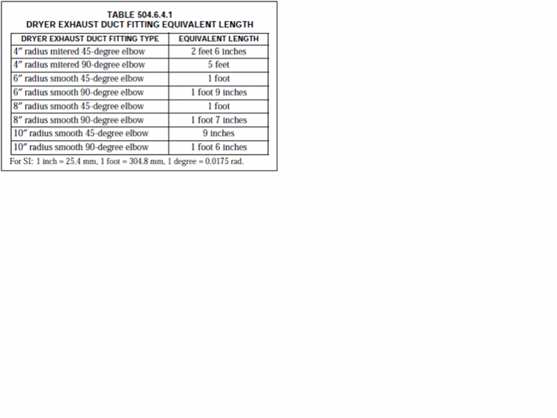
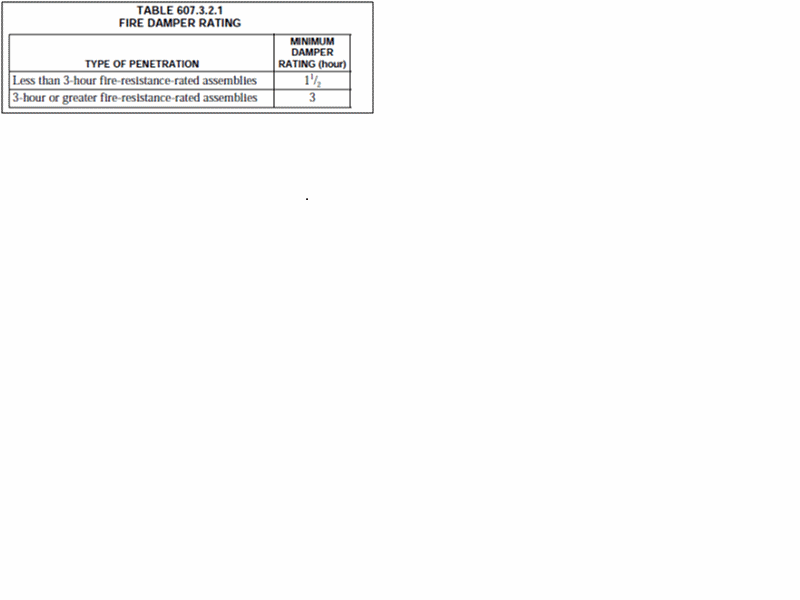

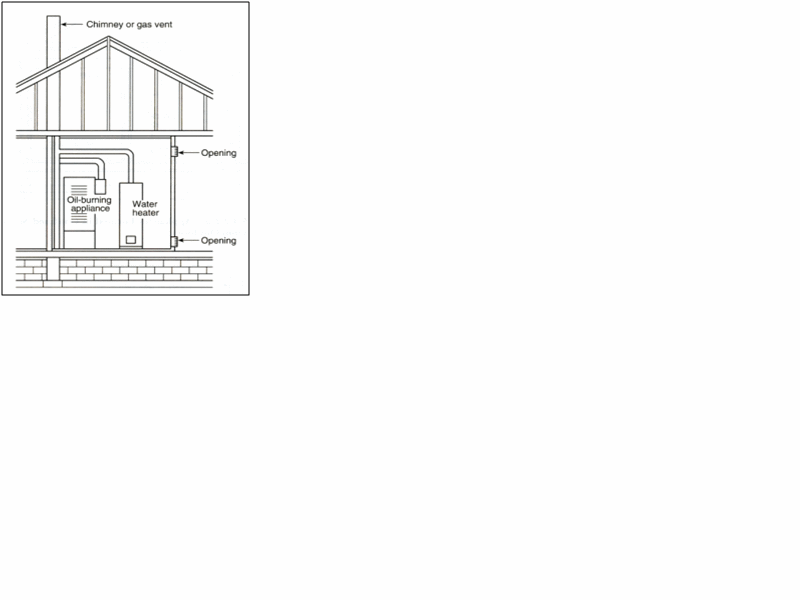
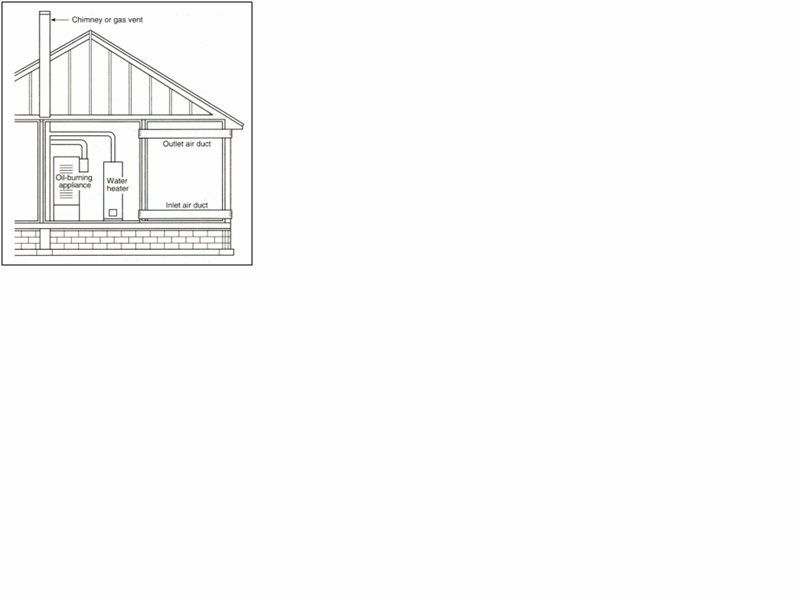
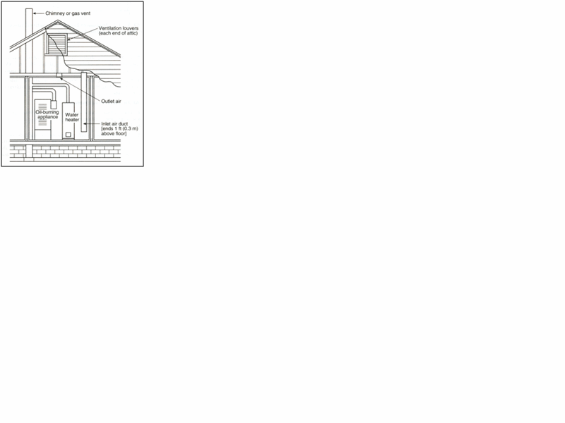

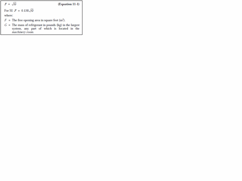


![[TOP]](/netaicon/toppg.gif)